Cirkit Designer
Your all-in-one circuit design IDE
Home /
Project Documentation
Arduino-Based Air Quality Monitoring System with MQ Sensors

Circuit Documentation
Summary
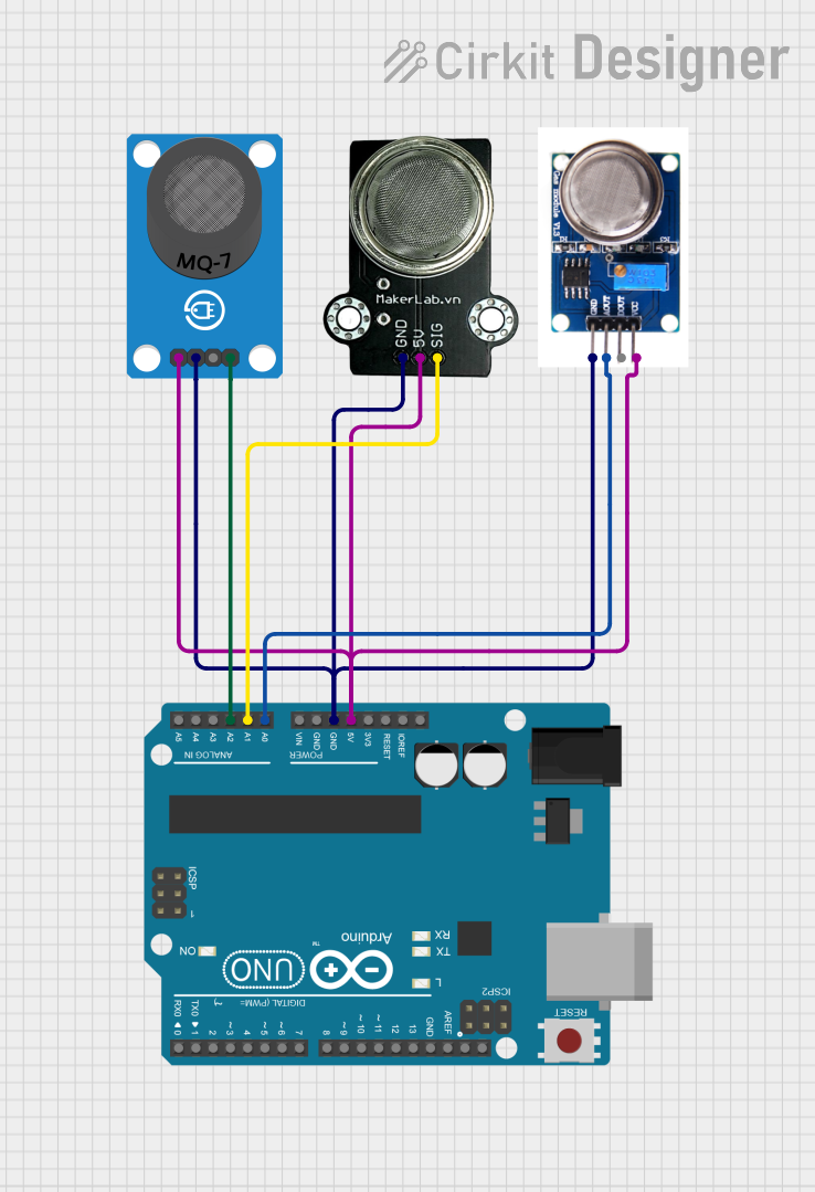
This circuit is designed to interface multiple gas sensors with an Arduino UNO microcontroller. The sensors used are the MQ-7, MQ131, and MQ-135, which detect carbon monoxide (CO), ozone (O3), and general air quality, respectively. The Arduino UNO reads the analog outputs from these sensors and prints the values to the serial monitor.
Component List
Arduino UNO
- Description: A microcontroller board based on the ATmega328P.
- Pins: UNUSED, IOREF, Reset, 3.3V, 5V, GND, Vin, A0, A1, A2, A3, A4, A5, SCL, SDA, AREF, D13, D12, D11, D10, D9, D8, D7, D6, D5, D4, D3, D2, D1, D0
- Purpose in Circuit: Acts as the main controller, reading sensor data and outputting it to the serial monitor.
MQ-7 Breakout
- Description: A sensor module for detecting carbon monoxide (CO).
- Pins: VCC, GND, DO, AO
- Purpose in Circuit: Provides an analog output (AO) proportional to the concentration of CO in the air.
MQ131
- Description: A sensor module for detecting ozone (O3).
- Pins: GND, AOUT, DOUT, VCC
- Purpose in Circuit: Provides an analog output (AOUT) proportional to the concentration of ozone in the air.
MKE-S09 MQ-135 Air Quality Sensor
- Description: A sensor module for detecting general air quality.
- Pins: GND, 5V, SIG
- Purpose in Circuit: Provides an analog output (SIG) proportional to the air quality.
Wiring Details
Arduino UNO
- 5V: Connected to VCC of MQ131, VCC of MQ-7 Breakout, and 5V of MQ-135.
- GND: Connected to GND of MQ131, GND of MQ-7 Breakout, and GND of MQ-135.
- A0: Connected to AOUT of MQ131.
- A1: Connected to SIG of MQ-135.
- A2: Connected to AO of MQ-7 Breakout.
MQ-7 Breakout
- VCC: Connected to 5V of Arduino UNO.
- GND: Connected to GND of Arduino UNO.
- AO: Connected to A2 of Arduino UNO.
MQ131
- VCC: Connected to 5V of Arduino UNO.
- GND: Connected to GND of Arduino UNO.
- AOUT: Connected to A0 of Arduino UNO.
MKE-S09 MQ-135 Air Quality Sensor
- 5V: Connected to 5V of Arduino UNO.
- GND: Connected to GND of Arduino UNO.
- SIG: Connected to A1 of Arduino UNO.
Code Documentation
int mq131Pin = A0;  // MQ131 connected to A0
int mq135Pin = A1;  // MQ135 connected to A1
int mq7Pin = A2;    // MQ7 connected to A2

void setup() {
  Serial.begin(9600);
}

void loop() {
  int mq131Value = analogRead(mq131Pin);  // Read value from MQ131
  int mq135Value = analogRead(mq135Pin);  // Read value from MQ135
  int mq7Value = analogRead(mq7Pin);      // Read value from MQ7

  Serial.print("MQ131 (Ozone): ");
  Serial.println(mq131Value);
  Serial.print("MQ135 (Air Quality): ");
  Serial.println(mq135Value);
  Serial.print("MQ7 (CO): ");
  Serial.println(mq7Value);

  delay(1000);  // Delay for readability
}
Code Explanation
- Pin Definitions: The analog pins A0, A1, and A2 on the Arduino UNO are assigned to the MQ131, MQ135, and MQ-7 sensors, respectively.
- Setup Function: Initializes the serial communication at a baud rate of 9600.
- Loop Function: Continuously reads the analog values from the sensors and prints them to the serial monitor with a delay of 1 second for readability.