Cirkit Designer
Your all-in-one circuit design IDE
Home /
Project Documentation
Raspberry Pi and H743-SLIM V3 Controlled Servo System with GPS and Telemetry
Circuit Documentation
Summary
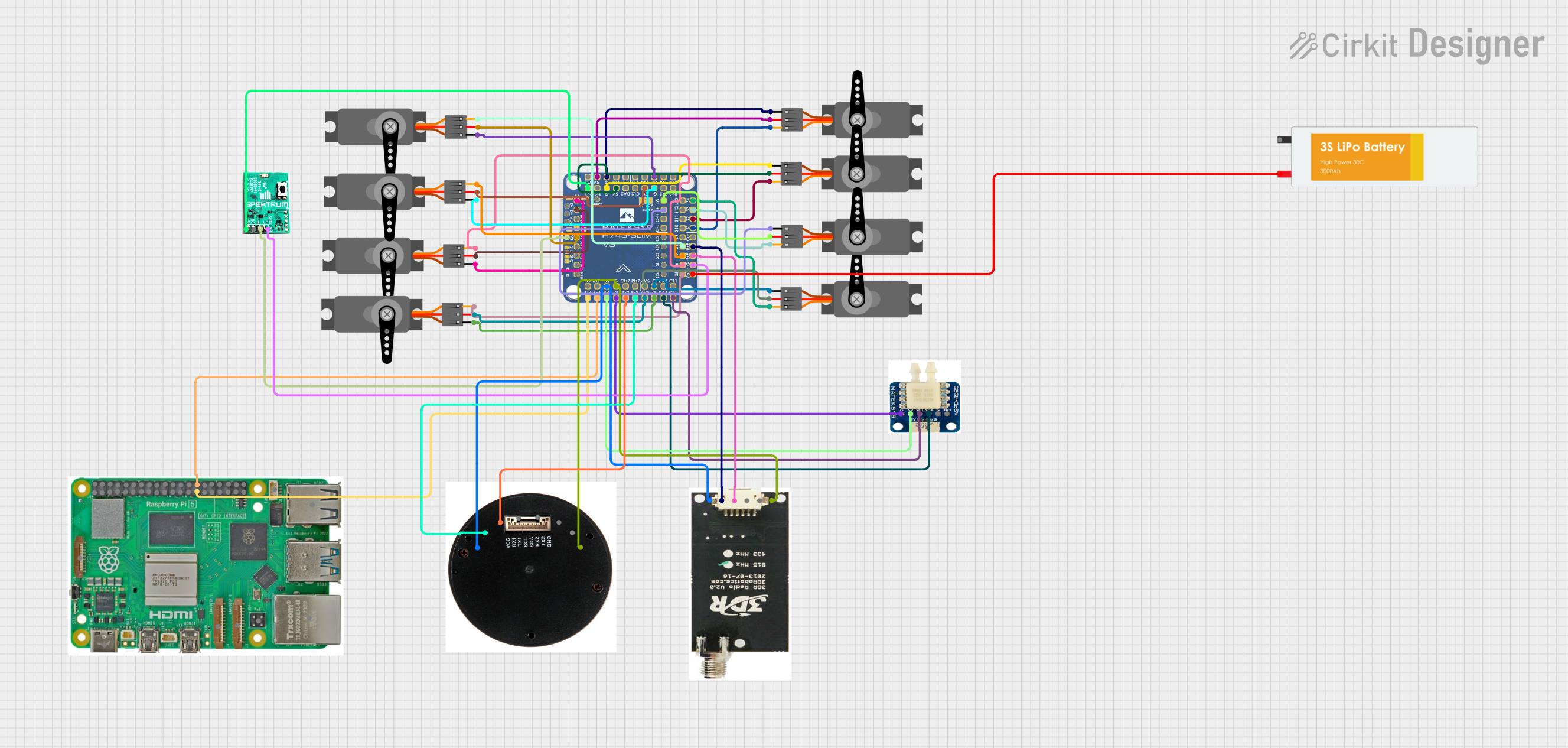
This document provides a detailed overview of a circuit that includes various components such as a Digital Airspeed Sensor, multiple Servos, a Raspberry Pi 5, an H743-SLIM V3 microcontroller, a Receiver, a GPS module, a Telemetry Radio, and a Lipo Battery. The circuit is designed to control multiple servos and gather data from sensors, with communication facilitated by the H743-SLIM V3 microcontroller.
Component List
Digital Airspeed Sensor
- Description: Measures airspeed.
- Pins: 5V, SCL, SDA, GND, 3V3
Servo
- Description: Actuator for mechanical movement.
- Pins: GND, VCC, PWM
Raspberry Pi 5
- Description: Single-board computer.
- Pins: Type-C, Micro HDMI 1, Micro HDMI 2, Camera 1, Camera 2, PoE, Fan, PCIe, USB 3.0, USB 2.0, Ethernet, 5V, GND, 3.3v, GPIO 14, GPIO 15, GPIO 18, GPIO 23, GPIO 24, GPIO 25, GPIO 8, GPIO 7, GPIO 1, GPIO 12, GPIO 16, GPIO 20, GPIO 21, GPIO 2, GPIO 3, GPIO 4, GPIO 17, GPIO 27, GPIO 22, GPIO 10, GPIO 9, GPIO 11, GPIO 0, GPIO 5, GPIO 6, GPIO 13, GPIO 19, GPIO 26
H743-SLIM V3
- Description: Microcontroller for controlling various components.
- Pins: VBAT (filtered), GND, TX8: UART8, Curr, S5, S6, S7, S8, S9, S10, S11, S1, S2, Tx7: UART7, RX7: UART7, 5V, Tx6: UART6, RX6: UART6, 4V5, TX2: UART2, RX2: UART2, Curr2, VBAT2, S3, S4, S12, LED, VSW, VTX: Video Out, TX4: UART4, RX4: UART4, RX3: UART3, TX3: UART3, RX1: UART1, TX1: UART1, Cam, Buz-, 3V3 (LDO), VBUS (USB), D- (USB), D+ (USB), C1: Camera 1, C2: Camera 2, CL: I2C2, DA2: I2C2, AirS, RSSI, DA1: I2C1, CL1: I2C1, Cts7: UART7 CTS/RTS, Rts7: UART7 CTS/RTS, RX8: UART8, SI: SPI3, SO: SPI3, SPI3, C-L: CAN-L, C-H: CAN-H, CS2, CS1
Receiver
- Description: Receives signals for control.
- Pins: Signal, No Connect, Positive, Negative
GPS
- Description: Provides location data.
- Pins: RX1, TX1, SCL, SDA, RX2, TX2, GND, VCC
Telemetry Radio
- Description: Facilitates wireless communication.
- Pins: GND, RTS, CTS, TX, RX, 5V
Lipo Battery
- Description: Power source.
- Pins: VCC, GND
Wiring Details
Digital Airspeed Sensor
- 5V: Connected to H743-SLIM V3 (4V5)
- GND: Connected to H743-SLIM V3 (GND)
- SCL: Connected to H743-SLIM V3 (CL1: I2C1)
- SDA: Connected to H743-SLIM V3 (DA1: I2C1)
Servo 1
- GND: Connected to H743-SLIM V3 (GND)
- VCC: Connected to H743-SLIM V3 (5V)
- PWM: Connected to H743-SLIM V3 (S1)
Servo 2
- GND: Connected to H743-SLIM V3 (GND)
- VCC: Connected to H743-SLIM V3 (5V)
- PWM: Connected to H743-SLIM V3 (S2)
Servo 3
- GND: Connected to H743-SLIM V3 (GND)
- VCC: Connected to H743-SLIM V3 (5V)
- PWM: Connected to H743-SLIM V3 (S3)
Servo 4
- GND: Connected to H743-SLIM V3 (GND)
- VCC: Connected to H743-SLIM V3 (4V5)
- PWM: Connected to H743-SLIM V3 (S4)
Servo 5
- GND: Connected to H743-SLIM V3 (GND)
- VCC: Connected to H743-SLIM V3 (4V5)
- PWM: Connected to H743-SLIM V3 (S5)
Servo 6
- GND: Connected to H743-SLIM V3 (GND)
- VCC: Connected to H743-SLIM V3 (5V)
- PWM: Connected to H743-SLIM V3 (S6)
Servo 7
- GND: Connected to H743-SLIM V3 (GND)
- VCC: Connected to H743-SLIM V3 (5V)
- PWM: Connected to H743-SLIM V3 (S7)
Servo 8
- GND: Connected to H743-SLIM V3 (GND)
- VCC: Connected to H743-SLIM V3 (5V)
- PWM: Connected to H743-SLIM V3 (S8)
Raspberry Pi 5
- GPIO 0: Connected to H743-SLIM V3 (Tx6: UART6)
- GPIO 1: Connected to H743-SLIM V3 (RX6: UART6)
H743-SLIM V3
- VBAT (filtered): Connected to Lipo Battery (VCC)
- GND: Connected to Receiver (Negative), GPS (GND), Telemetry Radio (GND), Digital Airspeed Sensor (GND), Servo 1 (GND), Servo 2 (GND), Servo 3 (GND), Servo 4 (GND), Servo 5 (GND), Servo 6 (GND), Servo 7 (GND), Servo 8 (GND)
- TX8: UART8: Connected to Telemetry Radio (TX)
- S5: Connected to Servo 5 (PWM)
- S6: Connected to Servo 6 (PWM)
- S7: Connected to Servo 7 (PWM)
- S8: Connected to Servo 8 (PWM)
- S1: Connected to Servo 1 (PWM)
- S2: Connected to Servo 2 (PWM)
- 5V: Connected to GPS (VCC), Telemetry Radio (5V), Servo 1 (VCC), Servo 2 (VCC), Servo 3 (VCC), Servo 6 (VCC), Servo 7 (VCC), Servo 8 (VCC)
- Tx6: UART6: Connected to Raspberry Pi 5 (GPIO 0)
- RX6: UART6: Connected to Raspberry Pi 5 (GPIO 1)
- 4V5: Connected to Digital Airspeed Sensor (5V), Servo 4 (VCC), Servo 5 (VCC)
- TX2: UART2: Connected to GPS (TX1)
- RX2: UART2: Connected to GPS (RX1)
- RX1: UART1: Connected to Receiver (Signal)
- 3V3 (LDO): Connected to Receiver (Positive)
- DA1: I2C1: Connected to Digital Airspeed Sensor (SDA)
- CL1: I2C1: Connected to Digital Airspeed Sensor (SCL)
- RX8: UART8: Connected to Telemetry Radio (RX)
Receiver
- Signal: Connected to H743-SLIM V3 (RX1: UART1)
- Positive: Connected to H743-SLIM V3 (3V3 (LDO))
- Negative: Connected to H743-SLIM V3 (GND)
GPS
- RX1: Connected to H743-SLIM V3 (RX2: UART2)
- TX1: Connected to H743-SLIM V3 (TX2: UART2)
- GND: Connected to H743-SLIM V3 (GND)
- VCC: Connected to H743-SLIM V3 (5V)
Telemetry Radio
- TX: Connected to H743-SLIM V3