
ESP32-Based Automated Irrigation and Motor Control System with Blynk App Integration
View and Edit Project In Cirkit Designer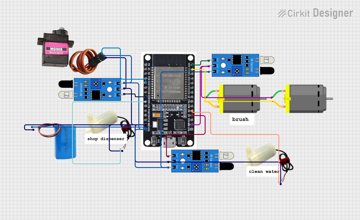
Circuit Documentation
Summary
The circuit in question is designed to interface an ESP32 microcontroller with multiple sensors and actuators, including IR sensors, DC motors, and mini water pumps. The ESP32 is programmed to interact with these components based on sensor inputs and can be controlled remotely via the Blynk platform. The circuit is powered by a 5V battery, and the ground connections are shared among all components.
Component List
ESP32
- Microcontroller with WiFi capability.
- Utilized for reading sensor data, controlling motors and pumps, and communicating with the Blynk app.
IR Sensors
- Used to detect objects or movement.
- The output of these sensors is used to control the motors and pumps.
DC Motors
- Actuators that convert electrical energy into mechanical rotation.
- Controlled by the ESP32 based on IR sensor inputs.
5V Mini Water Pumps
- Small pumps powered by 5V used to move water or other liquids.
- Operated by the ESP32, again based on sensor feedback.
5V Battery
- Provides the power supply for the entire circuit.
MG90S
- A micro servo motor used for precise positioning.
- Receives control signals from the ESP32.
Wiring Details
ESP32
D35connected to MG90S SIG pin.D25connected to IR Sensor (IR3) output.D26connected to 5V Mini Water Pump (Pump1) positive pin.GNDconnected to common ground.VINconnected to 5V Battery positive pin.D2connected to IR Sensor (IR2) output.D4connected to 5V Mini Water Pump (Pump2) positive pin.D22connected to DC Motors pin 2.D23connected to IR Sensor (IR1) output.
IR Sensors
outof IR Sensor (IR1) connected toD23on ESP32.outof IR Sensor (IR2) connected toD2on ESP32.outof IR Sensor (IR3) connected toD25on ESP32.gndof all IR Sensors connected to common ground.vccof all IR Sensors connected toVINon ESP32.
DC Motors
pin 1of both DC Motors connected to common ground.pin 2of both DC Motors connected toD22on ESP32.
5V Mini Water Pumps
positive pinof Pump1 connected toD26on ESP32.positive pinof Pump2 connected toD4on ESP32.negative pinof both pumps connected to common ground.
5V Battery
positiveconnected toVINon ESP32.negativeconnected to common ground.
MG90S
SIGconnected toD35on ESP32.VCCconnected toVINon ESP32.GNDconnected to common ground.
Documented Code
#define BLYNK_TEMPLATE_ID "YourTemplateID"
#define BLYNK_DEVICE_NAME "YourDeviceName"
#define BLYNK_AUTH_TOKEN "YourAuthToken"

#include <WiFi.h>
#include <BlynkSimpleEsp32.h>

#define IR1_PIN 23
#define IR2_PIN 2
#define IR3_PIN 25

#define PUMP1_PIN 26
#define PUMP2_PIN 4
#define MOTOR_PIN 22

char auth[] = BLYNK_AUTH_TOKEN;
char ssid[] = "YourSSID";  // WiFi name
char pass[] = "YourPassword"; // WiFi password

BlynkTimer timer;

void checkSensors() {
  int ir1State = digitalRead(IR1_PIN);
  int ir2State = digitalRead(IR2_PIN);
  int ir3State = digitalRead(IR3_PIN);

  // Motor control according to ir1
  if (ir1State == LOW) {
    digitalWrite(MOTOR_PIN, HIGH); // Turn on motor
  } else {
    digitalWrite(MOTOR_PIN, LOW); // Turn off motor
  }

  // Pump 1 control according to ir3
  if (ir3State == LOW) {
    digitalWrite(PUMP1_PIN, HIGH); // Turn on pump1
  } else {
    digitalWrite(PUMP1_PIN, LOW); // Turn off pump1
  }

  // Pump 2 control according to ir2
  if (ir2State == LOW) {
    digitalWrite(PUMP2_PIN, HIGH); // Turn on pump2
  } else {
    digitalWrite(PUMP2_PIN, LOW); // Turn off pump2
  }
}

BLYNK_WRITE(V0) {
  int state = param.asInt();
  digitalWrite(MOTOR_PIN, state);
}

BLYNK_WRITE(V1) {
  int state = param.asInt();
  digitalWrite(PUMP1_PIN, state);
}

BLYNK_WRITE(V2) {
  int state = param.asInt();
  digitalWrite(PUMP2_PIN, state);
}

void setup() {
  Serial.begin(9600);
  pinMode(IR1_PIN, INPUT);
  pinMode(IR2_PIN, INPUT);
  pinMode(IR3_PIN, INPUT);

  pinMode(PUMP1_PIN, OUTPUT);
  pinMode(PUMP2_PIN, OUTPUT);
  pinMode(MOTOR_PIN, OUTPUT);

  Blynk.begin(auth, ssid, pass);

  timer.setInterval(1000L, checkSensors); // Check sensors every second
}

void loop() {
  Blynk.run();
  timer.run();
}
This code is designed to run on the ESP32 microcontroller. It sets up the device to connect to WiFi and the Blynk platform, reads the state of three IR sensors, and controls two water pumps and a motor based on the sensor inputs. It also defines virtual pins to control the motor and pumps through the Blynk app.