
Arduino UNO-Based Multifunctional Security System with RFID and Fingerprint Authentication
View and Edit Project In Cirkit Designer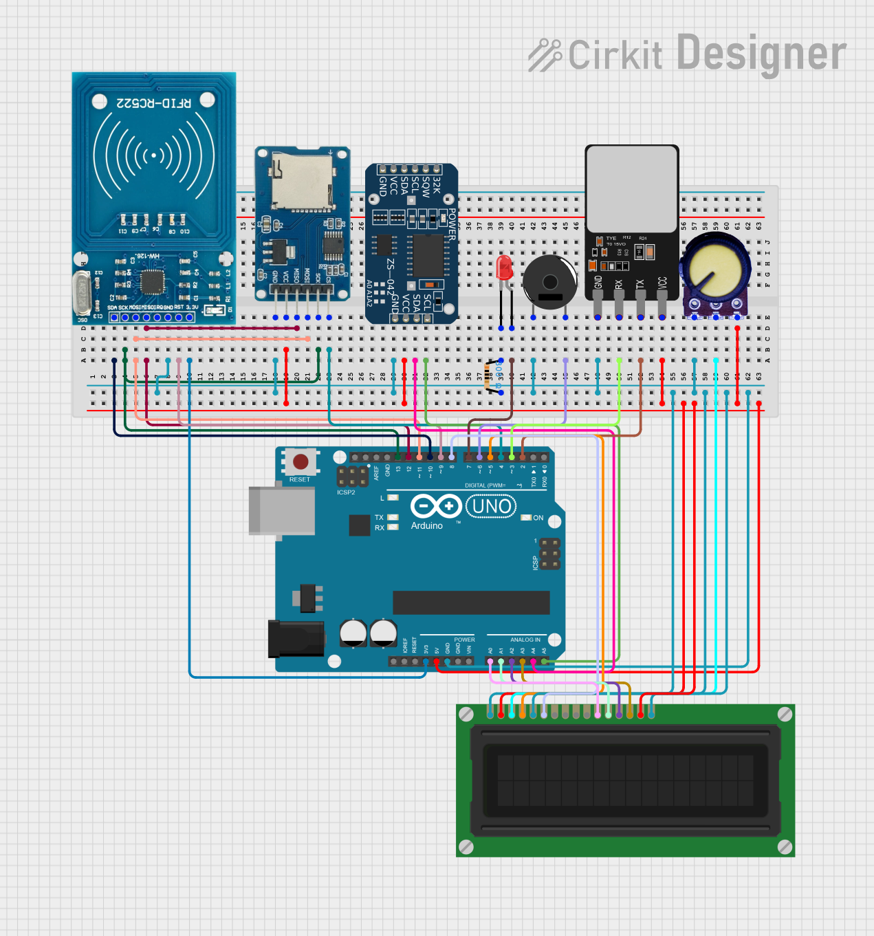
Circuit Documentation
Summary
This circuit integrates various components to interface with an Arduino UNO microcontroller. The components include an RFID-RC522 module for RFID communication, a Micro SD Card Module for data storage, a ZS-042 RTC Module for real-time clock capabilities, a red LED with a current-limiting resistor, a Piezo Buzzer for audio feedback, a Fingerprint Scanner for biometric input, an LCD Display for user interface, and a Potentiometer to adjust the LCD contrast. The Arduino UNO serves as the central processing unit, managing data flow and control logic for the entire system.
Component List
Micro SD Card Module
- Used for data storage.
- Pins: cs, sck, mosi, miso, vcc, gnd
RFID-RC522
- RFID communication module.
- Pins: VCC (3.3V), RST, GND, IRQ, MISO, MOSI, SCK, SDA
ZS-042 RTC Module
- Real-time clock module.
- Pins: 32K, SQW, SCL, SDA, VCC, GND
LED: Two Pin (red)
- Visual indicator.
- Pins: cathode, anode
Resistor (300 Ohms)
- Current-limiting resistor for the LED.
- Pins: pin1, pin2
Piezo Buzzer
- Audio feedback component.
- Pins: pin 1, pin 2
Fingerprint Scanner
- Biometric input device.
- Pins: VCC, TX, RX, GND
LCD Display (16 pin)
- User interface display.
- Pins: VSS, VDD, VO, RS, R_W, E, DB0, DB1, DB2, DB3, DB4, DB5, DB6, DB7, A, K
Potentiometer
- Variable resistor, typically for adjusting contrast on the LCD.
- Pins: GND, Output, VCC
Arduino UNO
- Microcontroller board serving as the central processing unit.
- Pins: UNUSED, IOREF, Reset, 3.3V, 5V, GND, Vin, A0, A1, A2, A3, A4, A5, SCL, SDA, AREF, D13, D12, D11, D10, D9, D8, D7, D6, D5, D4, D3, D2, D0
Wiring Details
Micro SD Card Module
- cs -> Arduino UNO (D4)
- sck -> Arduino UNO (D13)
- mosi -> Arduino UNO (D11)
- miso -> Arduino UNO (D12)
- vcc -> Arduino UNO (5V)
- gnd -> Common Ground Net
RFID-RC522
- SDA -> Arduino UNO (D10)
- SCK -> Arduino UNO (D13)
- MOSI -> Arduino UNO (D11)
- MISO -> Arduino UNO (D12)
- GND -> Common Ground Net
- RST -> Arduino UNO (D9)
- VCC (3.3V) -> Arduino UNO (3.3V)
ZS-042 RTC Module
- (No wiring details provided)
LED: Two Pin (red)
- anode -> Arduino UNO (D7)
- cathode -> Resistor (pin1)
Resistor (300 Ohms)
- pin1 -> LED (cathode)
- pin2 -> Common Ground Net
Piezo Buzzer
- pin 1 -> Common Ground Net
- pin 2 -> Arduino UNO (D6)
Fingerprint Scanner
- VCC -> Arduino UNO (5V)
- TX -> Arduino UNO (D2)
- RX -> Arduino UNO (D3)
- GND -> Common Ground Net
LCD Display (16 pin)
- VSS -> Common Ground Net
- VDD -> Arduino UNO (5V)
- VO -> Potentiometer (Output)
- RS -> Arduino UNO (D5)
- R_W -> Common Ground Net
- E -> Arduino UNO (D8)
- DB4 -> Arduino UNO (A0)
- DB5 -> Arduino UNO (A1)
- DB6 -> Arduino UNO (A2)
- DB7 -> Arduino UNO (A3)
- A -> Arduino UNO (5V)
- K -> Common Ground Net
Potentiometer
- GND -> Common Ground Net
- Output -> LCD Display (VO)
- VCC -> Arduino UNO (5V)
Documented Code
Arduino UNO Code (sketch.ino)
void setup() {
  // put your setup code here, to run once:

}

void loop() {
  // put your main code here, to run repeatedly:

}
Additional Notes
- The provided code is a template and does not include any functionality. The user must implement the setup and loop functions to control the circuit's components based on the project's requirements.
- The documentation file is empty and can be used to add detailed descriptions, usage instructions, or any other relevant information about the code and circuit operation.