
Arduino Nano-Based Weather Station with Wi-Fi Connectivity and Multiple AHT10 Sensors
View and Edit Project In Cirkit Designer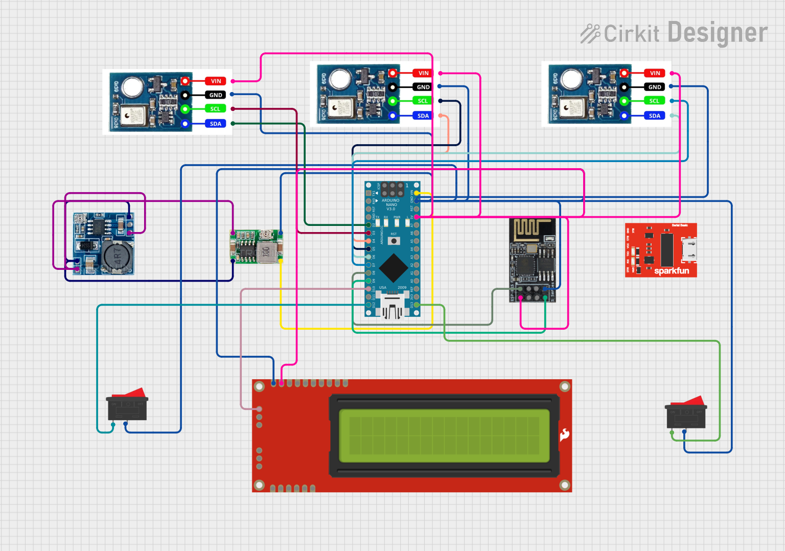
Circuit Documentation
Summary
This circuit involves an Arduino Nano microcontroller interfacing with multiple AHT10 temperature and humidity sensors, a WiFi module (ESP8266-01), a serial-enabled 16x2 LCD, and a couple of rocker switches. Power management is handled using a Mini 360 Buck Converter and a Step Down Module. The Arduino Nano is programmed to manage these components and facilitate communication between them.
Component List
Arduino Nano
- Description: A small, complete, and breadboard-friendly board based on the ATmega328P.
- Pins: D1/TX, D0/RX, RESET, GND, D2, D3, D4, D5, D6, D7, D8, D9, D10, D11/MOSI, D12/MISO, VIN, 5V, A7, A6, A5, A4, A3, A2, A1, A0, AREF, 3V3, D13/SCK
AHT10
- Description: A temperature and humidity sensor.
- Pins: Vcc, Gnd, SCL, SDA
Mini 360 Buck Converter
- Description: A step-down voltage converter.
- Pins: IN-, OUT-, OUT+, IN+
Step Down Module
- Description: A module to step down voltage from 24V to 5V.
- Pins: 24v IN+, GND, 12v IN+, 5v OUT+, 5v OUT-
WiFi Module ESP8266-01
- Description: A WiFi module for wireless communication.
- Pins: RX, GPIO0, GPIO2, GND, +3V3, Reset, CH-PD Chip power down, TX
SparkFun Serial Basic Breakout - CH340G
- Description: A USB to serial communication module.
- Pins: None
Serial Enabled 16x2 LCD - Black on Green 5V
- Description: A 16x2 character LCD display.
- Pins: GND, RX, VDD, RS, R/W, E, DB4, DB5, DB6, DB7, BL+, PGM, PGC, PGD, VPP
Rocker Switch
- Description: A simple on/off switch.
- Pins: 1, 2
Wiring Details
Arduino Nano
- D2: Connected to SDA of AHT10
- D3: Connected to SCL of AHT10
- D4: Connected to SDA of AHT10
- D5: Connected to SCL of AHT10
- D6: Connected to SDA of AHT10
- D7: Connected to SCL of AHT10
- D8: Connected to RX of WiFi module ESP8266-01
- D9: Connected to TX of WiFi module ESP8266-01
- D10: Connected to RX of Serial Enabled 16x2 LCD
- D12/MISO: Connected to pin 1 of Rocker Switch
- D13/SCK: Connected to pin 1 of Rocker Switch
- VIN: Connected to OUT+ of Mini 360 Buck Converter
- GND: Connected to GND of AHT10, Serial Enabled 16x2 LCD, Rocker Switch, WiFi module ESP8266-01, Mini 360 Buck Converter
AHT10
- SDA: Connected to D2, D4, D6 of Arduino Nano
- SCL: Connected to D3, D5, D7 of Arduino Nano
- Gnd: Connected to GND of Arduino Nano
- Vcc: Connected to 5V of Arduino Nano
Mini 360 Buck Converter
- IN-: Connected to GND of Step Down Module
- OUT-: Connected to GND of Arduino Nano
- OUT+: Connected to VIN of Arduino Nano
- IN+: Connected to 24v IN+ of Step Down Module
Step Down Module
- GND: Connected to IN- of Mini 360 Buck Converter
- 5v OUT-: Connected to GND of Step Down Module
- 24v IN+: Connected to IN+ of Mini 360 Buck Converter
- 5v OUT+: Connected to IN+ of Mini 360 Buck Converter
WiFi Module ESP8266-01
- RX: Connected to D8 of Arduino Nano
- TX: Connected to D9 of Arduino Nano
- GND: Connected to GND of Arduino Nano
- +3V3: Connected to 5V of Arduino Nano
Serial Enabled 16x2 LCD
- RX: Connected to D10 of Arduino Nano
- GND: Connected to GND of Arduino Nano
- VDD: Connected to 5V of Arduino Nano
Rocker Switch
- Pin 1: Connected to D12/MISO, D13/SCK of Arduino Nano
- Pin 2: Connected to GND of Arduino Nano
Documented Code
Arduino Nano Code (sketch.ino)
void setup() {
  // put your setup code here, to run once:

}

void loop() {
  // put your main code here, to run repeatedly:

}
Documentation (documentation.txt)
This documentation provides a comprehensive overview of the circuit, including a summary, detailed component list, wiring details, and the code used in the Arduino Nano.