
Arduino UNO and ESP32-CAM Based Smart Home Monitoring System with Battery Power
View and Edit Project In Cirkit Designer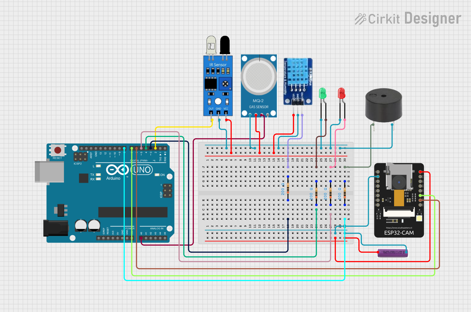
Circuit Documentation
Summary
This circuit involves an Arduino UNO microcontroller interfacing with various sensors, LEDs, a buzzer, and an ESP32-CAM module. The circuit is designed to monitor environmental conditions using sensors and provide visual and auditory feedback through LEDs and a buzzer. The ESP32-CAM module is powered by a 3.7V battery and is connected to the Arduino UNO for additional functionality.
Component List
LED: Two Pin (red)
- Pins: cathode, anode
- Description: Red LED for visual indication.
LED: Two Pin (green)
- Pins: cathode, anode
- Description: Green LED for visual indication.
Resistor (200 Ohms)
- Pins: pin1, pin2
- Description: Current limiting resistor for LEDs and other components.
MQ-2
- Pins: GND, VCC, ANALOG, Digital
- Description: Gas sensor for detecting various gases.
IR Sensor
- Pins: out, gnd, vcc
- Description: Infrared sensor for object detection.
Buzzer
- Pins: PIN, GND
- Description: Buzzer for auditory feedback.
Arduino UNO
- Pins: UNUSED, IOREF, Reset, 3.3V, 5V, GND, Vin, A0, A1, A2, A3, A4, A5, SCL, SDA, AREF, D13, D12, D11, D10, D9, D8, D7, D6, D5, D4, D3, D2, D1, D0
- Description: Microcontroller for controlling the circuit.
ESP32 - CAM
- Pins: 5V, GND, IO12, IO13, IO15, IO14, IO2, IO4, VOT, VOR, VCC, IO0, IO16, 3V3
- Description: Camera module with Wi-Fi capabilities.
3.7V Battery
- Pins: +, -
- Description: Power source for the ESP32-CAM module.
DHT11
- Pins: DATA, GND, VCC
- Description: Temperature and humidity sensor.
Wiring Details
LED: Two Pin (red)
- Anode connected to Resistor pin2.
- Cathode connected to GND.
LED: Two Pin (green)
- Anode connected to Resistor pin2.
- Cathode connected to GND.
Resistor (200 Ohms)
Resistor 1:
- Pin1 connected to Arduino UNO D3.
- Pin2 connected to DHT11 DATA.
Resistor 2:
- Pin1 connected to Arduino UNO D4.
- Pin2 connected to LED: Two Pin (green) anode.
Resistor 3:
- Pin1 connected to Arduino UNO D5.
- Pin2 connected to LED: Two Pin (red) anode.
Resistor 4:
- Pin1 connected to Arduino UNO D8.
- Pin2 connected to Buzzer PIN.
MQ-2
- GND connected to GND.
- VCC connected to VCC.
- ANALOG connected to Arduino UNO A0.
IR Sensor
- Out connected to Arduino UNO D2.
- GND connected to GND.
- VCC connected to VCC.
Buzzer
- PIN connected to Resistor pin2.
- GND connected to GND.
Arduino UNO
- D3 connected to Resistor pin1.
- D4 connected to Resistor pin1.
- D5 connected to Resistor pin1.
- D8 connected to Resistor pin1.
- A0 connected to MQ-2 ANALOG.
- D2 connected to IR Sensor out.
- D7 connected to ESP32 - CAM VOR.
- D6 connected to ESP32 - CAM VOT.
ESP32 - CAM
- 3V3 connected to 3.7V Battery +.
- GND connected to 3.7V Battery -.
- VOR connected to Arduino UNO D7.
- VOT connected to Arduino UNO D6.
3.7V Battery
- + connected to ESP32 - CAM 3V3.
- - connected to ESP32 - CAM GND.
DHT11
- DATA connected to Resistor pin2.
- GND connected to GND.
- VCC connected to VCC.
Documented Code
Arduino UNO Code (sketch.ino)
void setup() {
  // put your setup code here, to run once:

}

void loop() {
  // put your main code here, to run repeatedly:

}
Additional Documentation (documentation.txt)
This documentation provides a comprehensive overview of the circuit, including a summary, detailed component list, wiring details, and the code used in the microcontroller.