
Arduino Mega 2560 and ESP32-Based Smart Sensor System with Stepper Motor Control
View and Edit Project In Cirkit Designer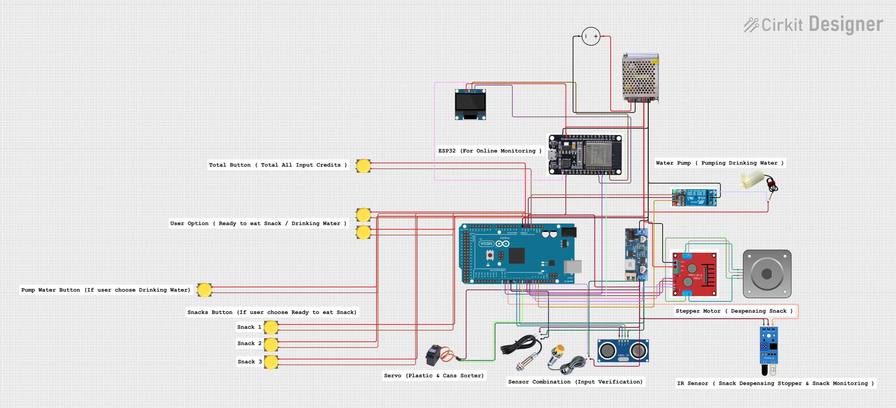
Circuit Documentation
Summary
This document provides a detailed overview of a circuit that includes various sensors, a stepper motor, a relay, a water pump, and two microcontrollers (Arduino Mega 2560 and ESP32). The circuit is powered by a 12V 5A power supply and includes a 12V to 5V step-down converter to power 5V components. The microcontrollers are programmed to control the sensors and actuators.
Component List
POWER SUPPLY 12V 5AMP
- Description: Provides 12V DC power from a 220V AC source.
- Pins: 220V Positive Pole (AC), 220V Negative Pole (AC), GND, GND (DC), 12V-24V Output (DC)
DC Power Source
- Description: Provides DC power.
- Pins: Ground, Positive
12v to 5v Step Down Power Converter
- Description: Converts 12V DC to 5V DC.
- Pins: VIN 9v-36v, VIN+, VIN-, USB OUTPUT 5V, 5v OUTPUT, GND
Inductive Sensor
- Description: Detects metallic objects.
- Pins: Signal, VCC, GND
Capacitive Sensor
- Description: Detects non-metallic objects.
- Pins: GND, VCC, SIGNAL
IR Sensor
- Description: Infrared sensor for object detection.
- Pins: out, gnd, vcc
Bipolar Stepper Motor (NEMA 17)
- Description: Stepper motor for precise control.
- Pins: A-, A+, B+, B-
HC-SR04 Ultrasonic Sensor
- Description: Measures distance using ultrasonic waves.
- Pins: VCC, TRIG, ECHO, GND
Motor Driver (L298N)
- Description: Drives the stepper motor.
- Pins: OUT 1, OUT 2, OUT 3, OUT 4, +12V INPUT, GND, +5V OUTPUT, ENA, IN 1, IN 2, IN 3, IN 4, ENB
MG996R
- Description: Servo motor.
- Pins: GND, VCC, SIG
Pushbutton
- Description: Simple pushbutton switch.
- Pins: Pin 2, Pin 1, Pin 3, Pin 4
5v Relay
- Description: Relay for switching high power devices.
- Pins: Normally Open, Common terminal, Normally Closed, In, GND, VCC
5v Mini Water Pump
- Description: Small water pump.
- Pins: positive pin, negative pin
Arduino Mega 2560
- Description: Microcontroller board.
- Pins: IOREF, RESET, 3V3, 5V, GND, VIN, A0-A15, D0-D53, SDA, SCL, AREF
ESP32
- Description: Microcontroller with Wi-Fi and Bluetooth.
- Pins: EN, VP, VN, D34, D35, D32, D33, D25, D26, D27, D14, D12, D13, GND, VIN, 3V3, D15, D2, D4, RX2, TX2, D5, D18, D19, D21, RX0, TX0, D22, D23, BOOT
0.96" OLED
- Description: Small OLED display.
- Pins: GND, VDD, SCK, SDA
Wiring Details
POWER SUPPLY 12V 5AMP
- 220V Positive Pole (AC): Connected to DC Power Source Positive
- 220V Negative Pole (AC): Connected to DC Power Source Ground
- GND (DC): Connected to various components' GND
- 12V-24V Output (DC): Connected to 12v to 5v Step Down Power Converter VIN+, Motor Driver (L298N) +12V INPUT, Arduino Mega 2560 VIN, ESP32 VIN, 5v relay Common terminal
DC Power Source
- Positive: Connected to POWER SUPPLY 12V 5AMP 220V Positive Pole (AC)
- Ground: Connected to POWER SUPPLY 12V 5AMP 220V Negative Pole (AC)
12v to 5v Step Down Power Converter
- VIN+: Connected to POWER SUPPLY 12V 5AMP 12V-24V Output (DC)
- VIN-: Connected to various components' GND
- 5v OUTPUT: Connected to IR Sensor vcc, HC-SR04 Ultrasonic Sensor VCC, Capacitive Sensor VCC, MG996R VCC, Inductive Sensor VCC
Inductive Sensor
- Signal: Connected to Arduino Mega 2560 D3 PWM
- VCC: Connected to 12v to 5v Step Down Power Converter 5v OUTPUT
- GND: Connected to various components' GND
Capacitive Sensor
- SIGNAL: Connected to Arduino Mega 2560 D4 PWM
- VCC: Connected to 12v to 5v Step Down Power Converter 5v OUTPUT
- GND: Connected to various components' GND
IR Sensor
- out: Connected to Arduino Mega 2560 D2 PWM
- vcc: Connected to 12v to 5v Step Down Power Converter 5v OUTPUT
- gnd: Connected to various components' GND
Bipolar Stepper Motor (NEMA 17)
- A+: Connected to Motor Driver (L298N) OUT 1
- A-: Connected to Motor Driver (L298N) OUT 2
- B+: Connected to Motor Driver (L298N) OUT 3
- B-: Connected to Motor Driver (L298N) OUT 4
HC-SR04 Ultrasonic Sensor
- ECHO: Connected to Arduino Mega 2560 D5 PWM
- TRIG: Connected to Arduino Mega 2560 D6 PWM
- VCC: Connected to 12v to 5v Step Down Power Converter 5v OUTPUT
- GND: Connected to various components' GND
Motor Driver (L298N)
- IN 1: Connected to Arduino Mega 2560 D8 PWM
- IN 2: Connected to Arduino Mega 2560 D9 PWM
- IN 3: Connected to Arduino Mega 2560 D10 PWM
- IN 4: Connected to Arduino Mega 2560 D11 PWM
- +12V INPUT: Connected to POWER SUPPLY 12V 5AMP 12V-24V Output (DC)
- GND: Connected to various components' GND
MG996R
- SIG: Connected to Arduino Mega 2560 D7 PWM
- VCC: Connected to 12v to 5v Step Down Power Converter 5v OUTPUT
- GND: Connected to various components' GND
Pushbutton
- Pin 1: Connected to various components' GND
- Pin 3: Connected to Arduino Mega 2560 5V
5v Relay
- In: Connected to Arduino Mega 2560 D12 PWM
- VCC: Connected to Arduino Mega 2560 5V
- GND: Connected to various components' GND
- Common terminal: Connected to POWER SUPPLY 12V 5AMP 12V-24V Output (DC)
- Normally Closed: Connected to 5v mini water pump positive pin
5v Mini Water Pump
- positive pin: Connected to 5v relay Normally Closed
- negative pin: Connected to various components' GND
Arduino Mega 2560
- 5V: Connected to Pushbutton Pin 3, 5v relay VCC
- GND: Connected to various components' GND
- VIN: Connected to POWER SUPPLY 12V 5AMP 12V-24V Output (DC)
- D0 RX0: Connected to ESP32 TX0
- D1 TX0: Connected to ESP32 RX0
- D2 PWM: Connected to IR Sensor out
- D3 PWM: Connected to Inductive Sensor Signal
- D4 PWM: Connected to Capacitive Sensor SIGNAL
- D5 PWM: Connected to HC-SR04 Ultrasonic Sensor ECHO
- D6 PWM: Connected to HC-SR04 Ultrasonic Sensor TRIG
- D7 PWM: Connected to MG996R SIG
- D8 PWM: Connected to Motor Driver (L298N) IN 1
- D9 PWM: Connected to Motor Driver (L298N) IN 2
- D10 PWM: Connected to Motor Driver (L298N) IN 3
- D11 PWM: Connected to Motor Driver (L298N) IN 4
- D12 PWM: Connected to 5v relay In
ESP32
- GND: Connected to various components' GND