Cirkit Designer
Your all-in-one circuit design IDE
Home /
Project Documentation
Arduino UNO-Based IR Transmitter with Multiple Pushbutton Controls and Battery Power
Circuit Documentation
Summary
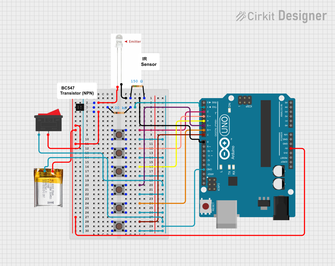
This circuit is designed to control an IR transmitter using an Arduino UNO microcontroller. The circuit includes multiple pushbuttons, resistors, a transistor, a LiPo battery, and a rocker switch. The pushbuttons are used to provide input to the Arduino, which then controls the IR transmitter. The circuit is powered by a 3.7V LiPo battery, and the rocker switch is used to turn the circuit on and off.
Component List
IR TX
- Pins: -, +
- Description: Infrared transmitter used to emit IR signals.
Pushbutton
- Pins: Pin 3 (out), Pin 4 (out), Pin 1 (in), Pin 2 (in)
- Description: Pushbutton used for user input.
Arduino UNO
- Pins: UNUSED, IOREF, Reset, 3.3V, 5V, GND, Vin, A0, A1, A2, A3, A4, A5, SCL, SDA, AREF, D13, D12, D11, D10, D9, D8, D7, D6, D5, D4, D3, D2, D1, D0
- Description: Microcontroller used to control the circuit.
Resistor (150 Ohms)
- Pins: pin1, pin2
- Description: Resistor used to limit current.
3.7V LiPo Battery
- Pins: +Ve, GND
- Description: Power source for the circuit.
Rocker Switch
- Pins: 1, 2
- Description: Switch used to turn the circuit on and off.
BC547 Transistor
- Pins: collector, base, emitter
- Description: NPN transistor used to amplify current.
Resistor (1000 Ohms)
- Pins: pin1, pin2
- Description: Resistor used to limit current.
Wiring Details
IR TX
- Pin -: Connected to pin1 of the 150 Ohms resistor and pin D8 of the Arduino UNO.
- Pin +: Connected to the emitter of the BC547 transistor.
Pushbutton 1
- Pin 3 (out): Connected to GND.
- Pin 1 (in): Connected to pin D7 of the Arduino UNO.
Pushbutton 2
- Pin 3 (out): Connected to GND.
- Pin 1 (in): Connected to pin D6 of the Arduino UNO.
Pushbutton 3
- Pin 3 (out): Connected to GND.
- Pin 1 (in): Connected to pin D5 of the Arduino UNO.
Pushbutton 4
- Pin 3 (out): Connected to GND.
- Pin 1 (in): Connected to pin D4 of the Arduino UNO.
Pushbutton 5
- Pin 3 (out): Connected to GND.
- Pin 1 (in): Connected to pin D3 of the Arduino UNO.
Pushbutton 6
- Pin 3 (out): Connected to GND.
- Pin 1 (in): Connected to pin D2 of the Arduino UNO.
Pushbutton 7
- Pin 3 (out): Connected to GND.
- Pin 1 (in): Connected to pin D1 of the Arduino UNO.
Arduino UNO
- Pin D8: Connected to pin1 of the 150 Ohms resistor and pin - of the IR TX.
- Pin D7: Connected to pin 1 (in) of Pushbutton 1.
- Pin D6: Connected to pin 1 (in) of Pushbutton 2.
- Pin D5: Connected to pin 1 (in) of Pushbutton 3.
- Pin D4: Connected to pin 1 (in) of Pushbutton 4.
- Pin D3: Connected to pin 1 (in) of Pushbutton 5.
- Pin D2: Connected to pin 1 (in) of Pushbutton 6.
- Pin D1: Connected to pin2 of the 1000 Ohms resistor.
- 5V: Connected to +Ve of the 3.7V LiPo battery, pin 2 of the rocker switch, and the collector of the BC547 transistor.
- GND: Connected to GND of the 3.7V LiPo battery, pin 1 of the rocker switch, and pin 3 (out) of all pushbuttons.
Resistor (150 Ohms)
- Pin 1: Connected to pin - of the IR TX and pin D8 of the Arduino UNO.
- Pin 2: Connected to pin1 of the 150 Ohms resistor.
3.7V LiPo Battery
- +Ve: Connected to pin 5V of the Arduino UNO, pin 2 of the rocker switch, and the collector of the BC547 transistor.
- GND: Connected to pin GND of the Arduino UNO, pin 1 of the rocker switch, and pin 3 (out) of all pushbuttons.
Rocker Switch
- Pin 1: Connected to GND of the 3.7V LiPo battery and pin GND of the Arduino UNO.
- Pin 2: Connected to +Ve of the 3.7V LiPo battery, pin 5V of the Arduino UNO, and the collector of the BC547 transistor.
BC547 Transistor
- Collector: Connected to +Ve of the 3.7V LiPo battery, pin 5V of the Arduino UNO, and pin 2 of the rocker switch.
- Base: Connected to pin1 of the 1000 Ohms resistor.
- Emitter: Connected to pin + of the IR TX.
Resistor (1000 Ohms)
- Pin 1: Connected to the base of the BC547 transistor.
- Pin 2: Connected to pin D1 of the Arduino UNO.
Documented Code
Arduino UNO Code (sketch.ino)
void setup() {
  // put your setup code here, to run once:

}

void loop() {
  // put your main code here, to run repeatedly:

}
Documentation (documentation.txt)