Arduino UNO-Based Automated Feeding System with SMS Alerts and Ultrasonic Level Sensing

Circuit Documentation
Summary
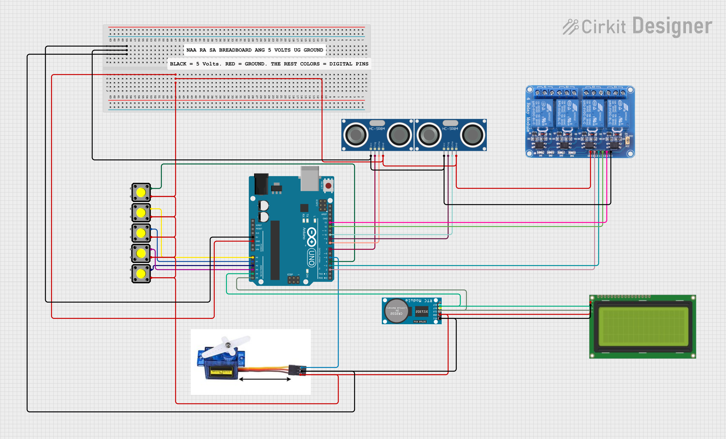
The circuit in question appears to be a complex system designed around an Arduino UNO microcontroller. It includes a variety of components such as a 4-channel 5V relay module, two HC-SR04 ultrasonic sensors, an RTC (Real-Time Clock), an I2C LCD display (20x4), multiple pushbuttons, a servo motor, and some comments which may represent annotations or placeholders for additional information. The circuit is likely intended for an application that involves time-based control of devices (via the relay), distance measurement (using ultrasonic sensors), and user interaction through buttons and display feedback.
Component List
- Arduino UNO: A microcontroller board based on the ATmega328P, featuring digital and analog I/O pins.
- Relay 4 Channel 5v: A relay module with four channels, allowing for the control of high-power devices.
- RTC (Real-Time Clock): A timekeeping device that maintains accurate time even when the main microcontroller is powered off.
- Pushbutton: A simple switch mechanism for control of a device or process.
- HC-SR04 Ultrasonic Sensor: A sensor that measures distance by emitting ultrasonic waves and measuring the time taken for the echo to return.
- Lcd 20x4 i2c: An LCD display with 20 characters per line and 4 lines, using the I2C communication protocol.
- Servo Motor 9G: A small and lightweight servo motor, commonly used for precise control of motion.
- Comment: Likely represents annotations or placeholders within the circuit design.
Wiring Details
Arduino UNO
- GND: Connected to the ground pins of the relay module, both ultrasonic sensors, the servo motor, the I2C LCD display, all pushbuttons, and the RTC.
- 5V: Powers the relay module, both ultrasonic sensors, the servo motor, the I2C LCD display, and the RTC.
- A0 - A3: Connected to various pushbuttons for user input.
- A4 (SDA): I2C data line connected to the I2C LCD display and RTC.
- A5 (SCL): I2C clock line connected to the I2C LCD display and RTC.
- D2 - D13: Various digital pins connected to the relay module and ultrasonic sensors, as well as a pushbutton and the servo motor.
Relay 4 Channel 5v
- GND: Connected to the Arduino's ground.
- VCC: Powered by the Arduino's 5V output.
- IN1 - IN4: Control inputs connected to various digital pins on the Arduino.
RTC
- VCC: Powered by the Arduino's 5V output.
- GND: Connected to the Arduino's ground.
- CLK: Connected to the Arduino's A5 (SCL) pin.
- DAT: Connected to the Arduino's A4 (SDA) pin.
Pushbuttons
- One side of each pushbutton is connected to the Arduino's ground.
- The other side of each pushbutton is connected to various analog pins on the Arduino for detecting button presses.
HC-SR04 Ultrasonic Sensors
- VCC: Powered by the Arduino's 5V output.
- GND: Connected to the Arduino's ground.
- TRIG: Trigger pins connected to various digital pins on the Arduino.
- ECHO: Echo pins connected to various digital pins on the Arduino.
Lcd 20x4 i2c
- GND: Connected to the Arduino's ground.
- 5v: Powered by the Arduino's 5V output.
- SCA: Connected to the Arduino's A4 (SDA) pin.
- SCL: Connected to the Arduino's A5 (SCL) pin.
Servo Motor 9G
- VCC 5V: Powered by the Arduino's 5V output.
- GND: Connected to the Arduino's ground.
- PMW: Control pin connected to a digital pin on the Arduino.
Documented Code
The code provided is for the Arduino UNO microcontroller and includes libraries for the RTC, I2C LCD, and Servo motor. It is designed to manage a feeding system, likely for animals or fish, with the ability to measure water level and feed levels, control relays for power management, and send SMS alerts for low levels or feeding times. The code includes functions for reading button states, measuring distances with ultrasonic sensors, controlling a servo motor, and sending SMS messages to predefined numbers.
#include <Wire.h>
#include <RTClib.h>
#include <LiquidCrystal_I2C.h>
#include <Servo.h>

// ... (Code omitted for brevity)

void setup() {
  // Initialization code for RTC, LCD, pins, servo, and GSM module
  // ...
}

void loop() {
  // Main loop handling button presses, relay activation, and display updates
  // ...
}

// Additional functions for button debouncing, distance measurement, relay control, etc.
// ...
The code is structured with a setup function to initialize the components and a loop function that continuously checks for button presses, updates the display, and activates relays at predefined times. There are also functions for measuring distance, displaying information, and sending SMS messages. The code is well-commented, making it easier to understand the functionality of each section.