
Battery-Powered Remote-Controlled Dual Motor System with Cytron URC10
View and Edit Project In Cirkit Designer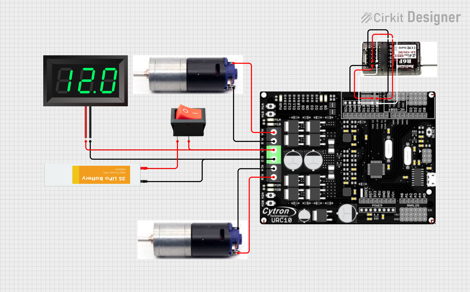
Circuit Documentation
Summary
This circuit is designed to control two GM25 DC motors using a Cytron URC10 motor driver, powered by a 3S LiPo battery. The circuit also includes a rocker switch for power control, a 7-segment panel voltmeter for voltage monitoring, and an R6FG receiver for remote control. The Cytron URC10 motor driver is programmed to receive signals from the R6FG receiver and control the motors accordingly.
Component List
Cytron URC10
- Description: Motor driver for controlling two DC motors.
- Pins: M1A, M1B, VM, GND, M2A, M2B, G, V, D10, D11
GM25 DC MOTOR (Motor 1)
- Description: DC motor for mechanical movement.
- Pins: +VE, -VE
GM25 DC MOTOR (Motor 2)
- Description: DC motor for mechanical movement.
- Pins: +VE, -VE
3S LIPO BATTERY
- Description: Power source for the circuit.
- Pins: -VE, +VE
Rocker Switch
- Description: Switch to control the power supply.
- Pins: Output, Input
7-Segment Panel Voltmeter
- Description: Displays the voltage of the power supply.
- Pins: V+, V-
R6FG RECEIVER
- Description: Receiver for remote control signals.
- Pins: GND, VCC, CH1, CH2
Wiring Details
Cytron URC10
- M1A connected to GM25 DC MOTOR (Motor 1) -VE
- M1B connected to GM25 DC MOTOR (Motor 1) +VE
- VM connected to 7-Segment Panel Voltmeter V+ and Rocker Switch Output
- GND connected to 7-Segment Panel Voltmeter V- and 3S LIPO BATTERY -VE
- M2A connected to GM25 DC MOTOR (Motor 2) -VE
- M2B connected to GM25 DC MOTOR (Motor 2) +VE
- G connected to R6FG RECEIVER GND
- V connected to R6FG RECEIVER VCC
- D10 connected to R6FG RECEIVER CH2
- D11 connected to R6FG RECEIVER CH1
GM25 DC MOTOR (Motor 1)
- -VE connected to Cytron URC10 M1A
- +VE connected to Cytron URC10 M1B
GM25 DC MOTOR (Motor 2)
- -VE connected to Cytron URC10 M2A
- +VE connected to Cytron URC10 M2B
3S LIPO BATTERY
- -VE connected to Cytron URC10 GND and 7-Segment Panel Voltmeter V-
- +VE connected to Rocker Switch Input
Rocker Switch
- Output connected to Cytron URC10 VM and 7-Segment Panel Voltmeter V+
- Input connected to 3S LIPO BATTERY +VE
7-Segment Panel Voltmeter
- V+ connected to Cytron URC10 VM and Rocker Switch Output
- V- connected to Cytron URC10 GND and 3S LIPO BATTERY -VE
R6FG RECEIVER
- GND connected to Cytron URC10 G
- VCC connected to Cytron URC10 V
- CH1 connected to Cytron URC10 D11
- CH2 connected to Cytron URC10 D10
Documented Code
// Almost same as URC10 Motor Driver Pins
#define leftPWM 5
#define leftDir 4
#define rightPWM 6
#define rightDir 7

// Receiver pins
#define RX_CH_1 11   // Steering Channel (Turn Left / Right)
#define RX_CH_2 10  // Throttle channel (Move Forward / Backward)

// Parameters
#define deadZone 50  // Anything between -20 and 20 is STOP

int throttleCH, steeringCH;
int leftMotorSpeed, rightMotorSpeed;

void setup() {
  Serial.begin(9600);
  pinMode(leftPWM, OUTPUT);
  pinMode(leftDir, OUTPUT);
  pinMode(rightPWM, OUTPUT);
  pinMode(rightDir, OUTPUT);
  pinMode(RX_CH_1, INPUT);
  pinMode(RX_CH_2, INPUT);

  digitalWrite(leftDir, LOW);
  analogWrite(leftPWM, 0);
  digitalWrite(rightDir, LOW);
  analogWrite(rightPWM, 0);
}

// Main Loop
void loop() {

  // Read pulse width from receiver
  throttleCH = pulseIn(RX_CH_2, HIGH, 30000);
  steeringCH = pulseIn(RX_CH_1, HIGH, 30000);
  // Serial.print(" steeringCH : ");
  // Serial.println(steeringCH);
  // Serial.print(" throttleCH: ");
  // Serial.println(steeringCH);

  // Convert to PWM value (-255 to 255)
  throttleCH = pulseToPWM(throttleCH);
  steeringCH = pulseToPWM(steeringCH);

  // Channel 1 and Channel 2 Mixing
  leftMotorSpeed = throttleCH - steeringCH;
  rightMotorSpeed = throttleCH + steeringCH;

  // Drive motor
  drive(leftMotorSpeed, rightMotorSpeed);
  //  Serial.print("  leftMotorSpeed : ");
  //  Serial.println(leftMotorSpeed);
  //  Serial.print("   rightMotorSpeed: ");
  //  Serial.println(rightMotorSpeed);

  delay(1);
}

// Positive for forward, negative for reverse
void drive(int leftVal, int rightVal) {

  // Limit speed between -255 and 255
  leftVal = constrain(leftVal, -255, 255);
  rightVal = constrain(rightVal, -255, 255);

  // Set direction for left motor
  if (leftVal == 0) {
    analogWrite(leftDir, 0);
    analogWrite(leftPWM, 0);
  } else if (leftVal > 0) {
    digitalWrite(leftDir, HIGH);
    analogWrite(leftPWM, abs(leftVal));
  } else {
    digitalWrite(leftDir, LOW);
    analogWrite(leftPWM, abs(leftVal));

  }

  // Set direction for right motor
  if (rightVal == 0) {
    analogWrite(rightDir, 0);
    analogWrite(rightPWM, 0);

  } else if (rightVal > 0) {
    digitalWrite(rightDir, HIGH);
    analogWrite(rightPWM, abs(rightVal));
  } else {
    digitalWrite(rightDir, LOW);
    analogWrite(rightPWM, abs(rightVal));

  }
}

// Convert RC pulse value to motor PWM value
int pulseToPWM(int pulse) {

  // If we're receiving numbers, convert them to motor PWM
  if (pulse > 500) {
    pulse = map(pulse, 1000, 2000, -500, 500);
    pulse = constrain(pulse, -255, 255);
  } else {
    pulse = 0;
  }

  // Anything in deadzone should stop the motor
  if (abs(pulse) <= deadZone) {
    pulse = 0;
  }
  return pulse;
}
This code is designed to control the motors based on the signals received from the R6FG receiver. The setup function initializes the pins and sets the initial motor states. The loop function reads the pulse width from the receiver, converts it to a PWM value, and drives the motors accordingly. The drive function sets the motor direction and speed, while the pulseToPWM function converts the RC pulse value to a motor PWM value.