
Arduino Mega 2560 Emergency Traffic Control System with RFID and I2C LCD
View and Edit Project In Cirkit Designer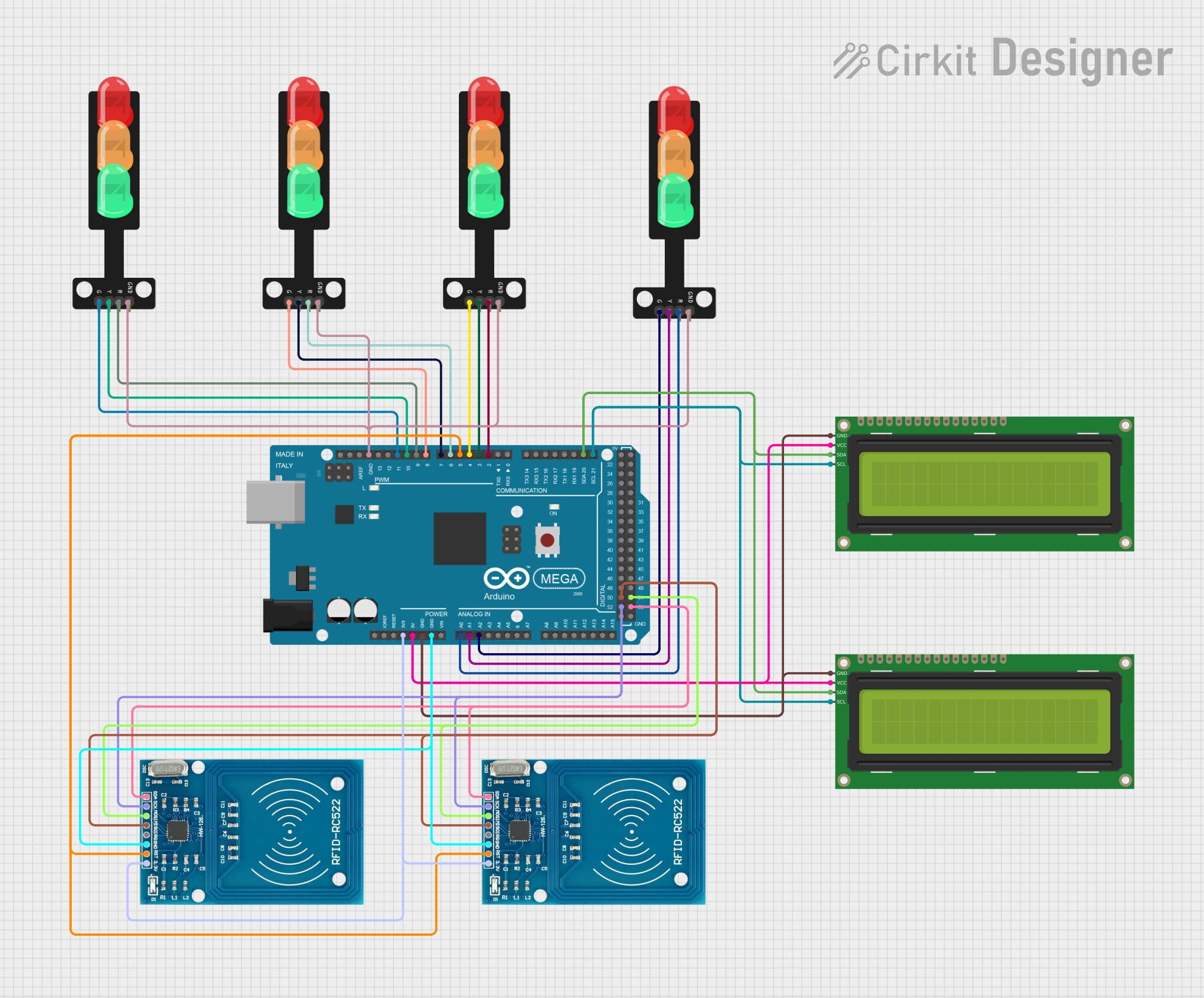
Circuit Documentation
Summary
This circuit is an Emergency Traffic Control System designed using an Arduino Mega 2560 microcontroller. The system includes multiple traffic light modules, RFID readers, and I2C LCD displays. The primary function of the system is to manage traffic lights and provide emergency control for ambulances using RFID tags. The system also displays messages on LCD screens.
Component List
Arduino Mega 2560
- Description: A microcontroller board based on the ATmega2560.
- Pins: IOREF, RESET, 3V3, 5V, GND, VIN, A0-A15, D0-D53, AREF, SDA, SCL
16x2 I2C LCD
- Description: A 16x2 character LCD display with I2C interface.
- Pins: GND, VCC, SDA, SCL
Traffic Light
- Description: A module representing a traffic light with red, yellow, and green LEDs.
- Pins: Green, Yellow, Red, GND
RFID-RC522
- Description: An RFID reader module.
- Pins: VCC (3.3V), RST, GND, IRQ, MISO, MOSI, SCK, SDA
Wiring Details
Arduino Mega 2560
- 3V3: Connected to VCC (3.3V) of both RFID-RC522 modules.
- 5V: Connected to VCC of both 16x2 I2C LCD modules.
- GND: Connected to GND of both 16x2 I2C LCD modules, both RFID-RC522 modules, and all Traffic Light modules.
- A0: Connected to Red pin of the first Traffic Light module.
- A1: Connected to Yellow pin of the first Traffic Light module.
- A2: Connected to Green pin of the first Traffic Light module.
- D2 PWM: Connected to Red pin of the second Traffic Light module.
- D3 PWM: Connected to Yellow pin of the second Traffic Light module.
- D4 PWM: Connected to Green pin of the second Traffic Light module.
- D5 PWM: Connected to RST pin of both RFID-RC522 modules.
- D6 PWM: Connected to Red pin of the third Traffic Light module.
- D7 PWM: Connected to Yellow pin of the third Traffic Light module.
- D8 PWM: Connected to Green pin of the third Traffic Light module.
- D9 PWM: Connected to Red pin of the fourth Traffic Light module.
- D10 PWM: Connected to Yellow pin of the fourth Traffic Light module.
- D11 PWM: Connected to Green pin of the fourth Traffic Light module.
- D21/SCL: Connected to SCL of both 16x2 I2C LCD modules.
- D20/SDA: Connected to SDA of both 16x2 I2C LCD modules.
- D52: Connected to SCK pin of both RFID-RC522 modules.
- D50: Connected to MISO pin of both RFID-RC522 modules.
- D53: Connected to SDA pin of both RFID-RC522 modules.
- D51: Connected to MOSI pin of both RFID-RC522 modules.
16x2 I2C LCD
- GND: Connected to GND of Arduino Mega 2560.
- VCC: Connected to 5V of Arduino Mega 2560.
- SDA: Connected to D20/SDA of Arduino Mega 2560.
- SCL: Connected to D21/SCL of Arduino Mega 2560.
Traffic Light
- Red: Connected to respective pins on Arduino Mega 2560 (A0, D2 PWM, D6 PWM, D9 PWM).
- Yellow: Connected to respective pins on Arduino Mega 2560 (A1, D3 PWM, D7 PWM, D10 PWM).
- Green: Connected to respective pins on Arduino Mega 2560 (A2, D4 PWM, D8 PWM, D11 PWM).
- GND: Connected to GND of Arduino Mega 2560.
RFID-RC522
- VCC (3.3V): Connected to 3V3 of Arduino Mega 2560.
- RST: Connected to D5 PWM of Arduino Mega 2560.
- GND: Connected to GND of Arduino Mega 2560.
- SCK: Connected to D52 of Arduino Mega 2560.
- MISO: Connected to D50 of Arduino Mega 2560.
- MOSI: Connected to D51 of Arduino Mega 2560.
- SDA: Connected to D53 of Arduino Mega 2560.
Documented Code
#include <SPI.h>
#include <MFRC522.h>
#include <Wire.h>
#include <LiquidCrystal_I2C.h>

// Define pins for traffic signal modules
int redPins[] = {2, 6, 9, A0};      // Red LEDs for each module
int greenPins[] = {4, 8, 11, A2};   // Green LEDs for each module

// Define the duration for the green light (10 seconds)
unsigned long greenLightDuration = 10000; // 10,000 milliseconds = 10 seconds

// Variable to track which module should have its green light on
int currentModule = 0;

// Variable to track the last time the green light changed
unsigned long lastChangeTime = 0;

// RFID reader setup
#define SS_PIN 53  // Change SS_PIN to 53 (instead of 10)
#define RST_PIN 5
MFRC522 mfrc522(SS_PIN, RST_PIN); // Create MFRC522 instance

// I2C LCD setup
LiquidCrystal_I2C lcd(0x27, 16, 2);  // Address 0x27, 16 columns and 2 rows

// States for the system
enum SystemState { GREEN_ROTATION, FIRST_MODULE_GREEN, EMERGENCY_MODE };
SystemState systemState = GREEN_ROTATION;

bool firstScanDone = false;

void setup() {
  // Initialize serial communication
  Serial.begin(9600);

  // Initialize RFID reader
  SPI.begin();
  mfrc522.PCD_Init();

  // Initialize the LCD
  lcd.begin(16, 2);  // Initialize with the LCD's dimensions
  lcd.clear();

  // Ensure the backlight is on
  lcd.backlight();   // Turn on the LCD backlight

  // Set all pins as OUTPUT
  for (int i = 0; i < 4; i++) {
    pinMode(redPins[i], OUTPUT);
    pinMode(greenPins[i], OUTPUT);
  }

  // Initialize all LEDs to off state (red on, green off)
  for (int i = 0; i < 4; i++) {
    digitalWrite(redPins[i], HIGH);   // Turn on red light initially
    digitalWrite(greenPins[i], LOW);  // Ensure green light is off initially
  }

  // Set the initial state (green signal rotation)
  lastChangeTime = millis(); // Initialize the start time for the first green light

  // Show initial message on the LCD
  lcd.setCursor(0, 0);
  lcd.print("Emergency Traffic");
  lcd.setCursor(0, 1);
  lcd.print("Control System");
}

void loop() {
  // Check if an RFID tag has been scanned
  if (mfrc522.PICC_IsNewCardPresent()) {
    if (mfrc522.PICC_ReadCardSerial()) {
      String tagUID = "";
      for (byte i = 0; i < mfrc522.uid.size; i++) {
        tagUID += String(mfrc522.uid.uidByte[i], HEX);
      }
      Serial.println("Tag UID: " + tagUID);

      // Handle the scan event based on whether it's the first or second scan
      if (!firstScanDone) {
        // First scan: display Ambulance message
        firstScanDone = true;

        // Switch to Emergency Mode
        systemState = EMERGENCY_MODE;

        // Set emergency signal (green for first module)
        digitalWrite(greenPins[0], HIGH);
        digitalWrite(redPins[0], LOW);
        for (int i = 1; i < 4; i++) {
          digitalWrite(greenPins[i], LOW);
          digitalWrite(redPins[i], HIGH);
        }

        // Show Ambulance message on LCD
        lcd.clear();
        lcd.setCursor(0, 0);
        lcd.print("Ambulance Nearby");
        lcd.setCursor(0, 1);
        lcd.print("PleaseCo-operate");

      } else {
        // Second scan: Reset system and display control system message
        firstScanDone = false;

        // Reset the system state to GREEN_ROTATION
        systemState = GREEN_ROTATION;
        lastChangeTime = millis(); // Reset the timer for green light rotation

        // Ensure the first module's green light is turned off before starting rotation again
        digitalWrite(greenPins[0], LOW);
        digitalWrite(redPins[0], HIGH);

        // Move to the second module for rotation start
        currentModule = 1; // Start