
Wi-Fi Enabled Motion and Orientation Sensor with ESP8266 and MPU6050
View and Edit Project In Cirkit Designer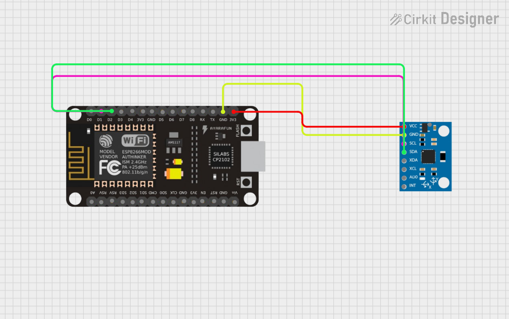
Circuit Documentation
Summary
This document provides a detailed overview of a circuit that integrates an ESP8266 NodeMCU microcontroller with an MPU6050 sensor. The ESP8266 NodeMCU is used to interface with the MPU6050 sensor to read accelerometer and gyroscope data. The connections between the components are established through specific pins, and the power and ground connections are also detailed.
Component List
ESP8266 NodeMCU
- Description: A low-cost Wi-Fi microcontroller with GPIO, PWM, ADC, I2C, and UART capabilities.
- Pins: D0, D1, D2, D3, D4, 3V3, GND, D5, D6, D7, D8, RX, TX, A0, RSV, SD3, SD2, SD1, CMD, SD0, CLK, EN, RST, VIN
MPU6050
- Description: A 6-axis motion tracking device that combines a 3-axis gyroscope and a 3-axis accelerometer.
- Pins: vcc, gnd, scl, sda, xda, xcl, AD0, int, 3.3v
Wiring Details
ESP8266 NodeMCU
- D1: Connected to MPU6050 scl
- D2: Connected to MPU6050 sda
- GND: Connected to MPU6050 gnd
- 3V3: Connected to MPU6050 vcc
MPU6050
- scl: Connected to ESP8266 NodeMCU D1
- sda: Connected to ESP8266 NodeMCU D2
- gnd: Connected to ESP8266 NodeMCU GND
- vcc: Connected to ESP8266 NodeMCU 3V3
Code
No code is provided for this circuit.
This document provides a comprehensive overview of the components and their connections in the circuit. The ESP8266 NodeMCU and MPU6050 are connected via I2C communication, with the necessary power and ground connections established.