
Arduino Mega 2560 and ESP32-Based Smart Home Automation System with Touch LCD and RTC
View and Edit Project In Cirkit Designer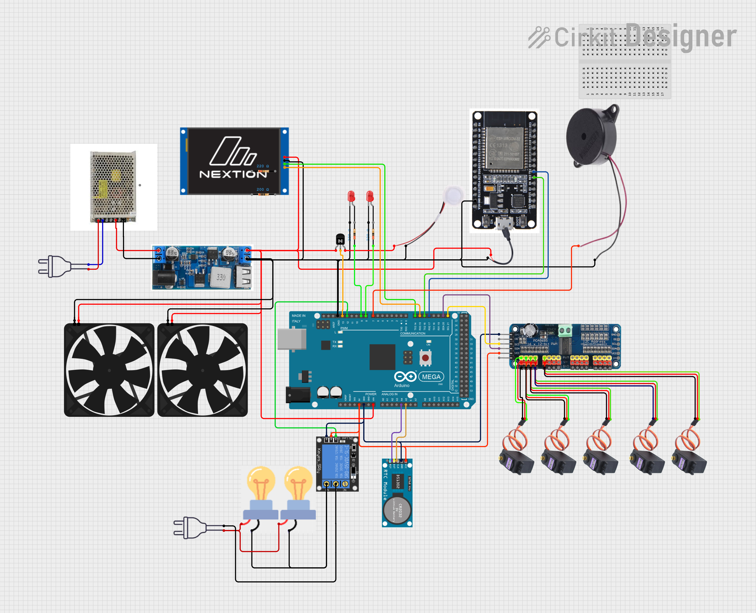
Circuit Documentation
Summary
This circuit involves an Arduino Mega 2560 microcontroller interfacing with various components including a Real-Time Clock (RTC), a 16-Channel PWM Servo Driver, a 1-Channel Relay, multiple MG996R servos, a Nextion Touch LCD, a fan, a humidifier, and other components. The circuit is powered by a 24V DC power supply, which is stepped down to 12V using a buck converter. The Arduino Mega 2560 controls the relay, servos, and other peripherals, while the ESP32 is used for additional processing and communication.
Component List
Arduino Mega 2560
- Description: Microcontroller board based on the ATmega2560.
- Pins: IOREF, RESET, 3V3, 5V, GND, VIN, A0-A15, D0-D53, AREF, SDA, SCL
Power Supply 24 VDC
- Description: Provides 24V DC power.
- Pins: L, N, E, V+, V-
1-Channel Relay (5V 10A)
- Description: Relay module for switching high-power devices.
- Pins: NC, signal, C, power, NO, ground
Bulb
- Description: Standard light bulb.
- Pins: GND, power
Power 220V
- Description: Standard 220V AC power source.
- Pins: hot wire, neutral wire
NPN Transistor (CBE)
- Description: NPN transistor for switching applications.
- Pins: collector, base, emitter
24/12V Buck Converter
- Description: Steps down 24V to 12V.
- Pins: VIN+, VIN-, 5V, GND
RTC
- Description: Real-Time Clock module.
- Pins: VCC, GND, CLK, DAT, RST
MG996R Servo
- Description: High-torque servo motor.
- Pins: GND, VCC, SIG
Nextion Touch LCD 2.4"
- Description: Touchscreen LCD display.
- Pins: VCC, GND, RX, TX
LED: Two Pin (red)
- Description: Standard red LED.
- Pins: cathode, anode
Resistor
- Description: Resistor with various resistance values.
- Pins: pin1, pin2
- Properties: 220 Ohms, 200 Ohms
Buzzer
- Description: Standard buzzer.
- Pins: POSITIVE, NEGATIVE
Fan
- Description: Standard fan.
- Pins: GND, 5V
ESP32
- Description: Microcontroller with Wi-Fi and Bluetooth capabilities.
- Pins: EN, VP, VN, D34, D35, D32, D33, D25, D26, D27, D14, D12, D13, GND, VIN, 3V3, D15, D2, D4, RX2, TX2, D5, D18, D19, D21, RX0, TX0, D22, D23, BOOT
16-Channel PWM Servo Driver
- Description: PWM driver for controlling multiple servos.
- Pins: V+, VCC, SDA, SCL, OE, GND, Vin+, Vin-, PWM1-PWM16
Humidifier
- Description: Standard humidifier.
- Pins: GND, 5V
Micro USB to Cable (2 Pin)
- Description: Micro USB to 2-pin cable.
- Pins: Micro USB, +, -
Wiring Details
Arduino Mega 2560
- 5V: Connected to VCC of RTC, VCC of 16-Channel PWM Servo Driver, power of 1-Channel Relay
- GND: Connected to GND of RTC, GND of 16-Channel PWM Servo Driver, ground of 1-Channel Relay, GND of Fan, GND of Humidifier, cathode of LED (red), GND of Nextion Touch LCD, GND of ESP32, GND of 24/12V Buck, NEGATIVE of Buzzer, GND of Fan
- VIN: Connected to collector of NPN Transistor, + of Micro USB to Cable, VCC of Nextion Touch LCD, 5V of 24/12V Buck
- A4: Connected to DAT of RTC
- A5: Connected to CLK of RTC
- D21/SCL: Connected to SCL of 16-Channel PWM Servo Driver
- D20/SDA: Connected to SDA of 16-Channel PWM Servo Driver
- D17 PWM/RX2: Connected to TX2 of ESP32
- D16 PWM/TX2: Connected to RX2 of ESP32
- D15/RX3: Connected to RX of Nextion Touch LCD
- D14/TX3: Connected to TX of Nextion Touch LCD
- D7 PWM: Connected to POSITIVE of Buzzer
- D8 PWM: Connected to pin1 of Resistor (220 Ohms)
- D9 PWM: Connected to pin1 of Resistor (220 Ohms)
- D12 PWM: Connected to signal of 1-Channel Relay
- D13 PWM: Connected to base of NPN Transistor
Power Supply 24 VDC
- L: Connected to hot wire of Power 220V
- N: Connected to neutral wire of Power 220V
- V+: Connected to VIN+ of 24/12V Buck
- V-: Connected to VIN- of 24/12V Buck
1-Channel Relay (5V 10A)
- power: Connected to 5V of Arduino Mega 2560
- ground: Connected to GND of Arduino Mega 2560
- signal: Connected to D12 PWM of Arduino Mega 2560
- C: Connected to neutral wire of Power 220V
- NO: Connected to GND of Bulb
Bulb
- GND: Connected to NO of 1-Channel Relay
- power: Connected to hot wire of Power 220V
NPN Transistor (CBE)
- collector: Connected to 5V of Fan, + of Micro USB to Cable, VIN of Arduino Mega 2560, VCC of Nextion Touch LCD, 5V of 24/12V Buck
- base: Connected to D13 PWM of Arduino Mega 2560
- emitter: Connected to 5V of Humidifier
24/12V Buck Converter
- VIN+: Connected to V+ of Power Supply 24 VDC
- VIN-: Connected to V- of Power Supply 24 VDC
- 5V: Connected to collector of NPN Transistor, + of Micro USB to Cable, VIN of Arduino Mega 2560, VCC of Nextion Touch LCD, 5V of Fan
RTC
- VCC: Connected to 5V of Arduino Mega 2560
- GND: Connected to GND of Arduino Mega 2560
- DAT: Connected to A4 of Arduino Mega 2560
- CLK: Connected to A5 of Arduino Mega 2560
MG996R Servo
- GND: Connected to GND of 16-Channel PWM Servo Driver
- VCC: Connected to V+ of 16-Channel PWM Servo Driver
- SIG: Connected to PWM1-PWM5 of 16-Channel PWM Servo Driver
Nextion Touch LCD 2.4"
- VCC: Connected to VIN of Arduino Mega 2560
- GND: Connected to GND of Arduino Mega 2560
- RX: Connected to D15/RX3 of Arduino Mega 2560
- TX: Connected to D14/TX3 of Arduino Mega 2560
LED: Two Pin (red)
- cathode: Connected to GND of Arduino Mega 2560
- anode: Not connected
Resistor
- pin1: Connected to D8 PWM, D9 PWM of Arduino Mega 2560
- pin2: Not connected
Buzzer
- POSITIVE: Connected to D7 PWM of Arduino Mega 2560
- NEGATIVE: Connected to GND of Arduino Mega 2560
Fan
- GND: Connected to GND of Arduino Mega 2560
- 5V: Connected to collector of NPN Transistor
ESP32
- TX2: Connected to D17 PWM/RX2 of Arduino Mega 2560
- RX2: Connected to D16 PWM/TX2 of Arduino Mega 2560
- GND: Connected to GND of Arduino Mega 2560
16-Channel PWM Servo Driver
- V+: Connected to VCC of MG996R Servo
- VCC: Connected to 5V of Arduino Mega 2560
- SDA: Connected to D20/SDA of Arduino Mega 2560
- SCL: Connected to