
Teensy 4.1-Based Multi-Channel Potentiometer Interface with 74HC4051 Mux and AMS1117 3.3V Regulator
View and Edit Project In Cirkit Designer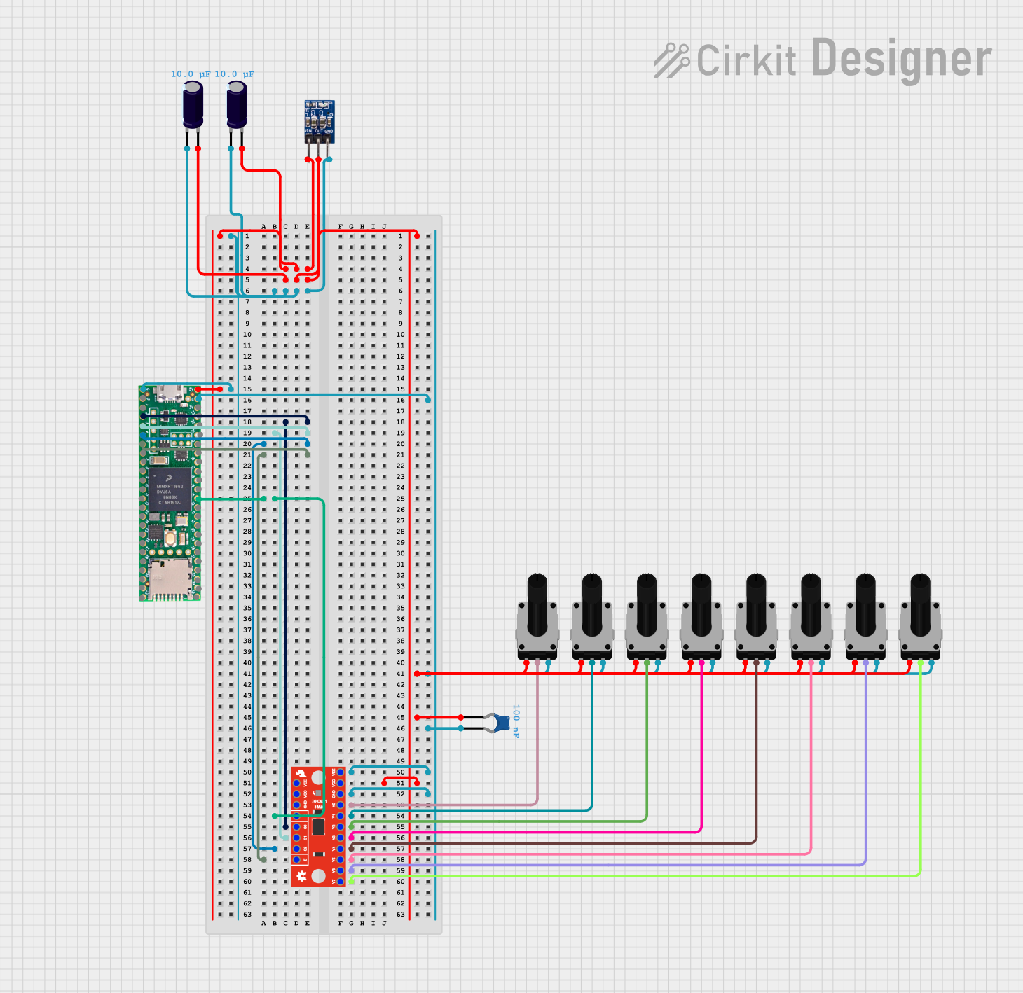
Circuit Documentation
Summary
This document provides a detailed overview of a circuit design that includes various components such as capacitors, a voltage regulator, a multiplexer, and a microcontroller. The circuit is designed to manage power distribution, signal multiplexing, and user input through potentiometers. The document includes a component list, wiring details, and code documentation.
Component List
Electrolytic Capacitor
- Description: Electrolytic capacitors are polarized capacitors used in various applications for filtering, decoupling, and energy storage.
- Pins: -, +
- Properties:
- Capacitance: 10 µF
AMS1117 3.3
- Description: A voltage regulator that provides a stable 3.3V output from a higher input voltage.
- Pins: VIN, OUT, GND
Ceramic Capacitor
- Description: Non-polarized capacitors used for high-frequency applications and decoupling.
- Pins: pin0, pin1
- Properties:
- Capacitance: 100 nF
Rotary Potentiometer
- Description: Variable resistors used to adjust voltage levels in a circuit.
- Pins: leg1, wiper, leg2
- Properties:
- Resistance: 10 kΩ
SparkFun 74HC4051 8-Channel Mux Breakout
- Description: A multiplexer that allows multiple analog or digital signals to be routed to a single output.
- Pins: Y7, Y6, Y5, Y4, Y3, Y2, Y1, Y0, GND, VCC, VEE, !E!, S2, S1, S0, Z
Teensy 4.1
- Description: A powerful microcontroller board used for various embedded applications.
- Pins: Ground, 0, 1, 2, 3, 4, 5, 6, 7, 8, 9, 10, 11, 12, 3v, 24, 25, 26, 27, 28, 29, 30, 31, 32, 5V/Input, 3V, 23, 22, 21, 20, 19, 18, 17, 16, 15, 14, 13, 41, 40, 39, 38, 37, 36, 35, 34, 33
Wiring Details
Electrolytic Capacitor
Capacitor 1:
- + Pin: Connected to VIN of AMS1117 3.3 and 5V/Input of Teensy 4.1
- - Pin: Connected to GND of AMS1117 3.3 and Ground of Teensy 4.1
Capacitor 2:
- + Pin: Connected to OUT of AMS1117 3.3, VCC of SparkFun 74HC4051, and leg1 of all Rotary Potentiometers
- - Pin: Connected to GND of AMS1117 3.3 and Ground of Teensy 4.1
AMS1117 3.3
- VIN: Connected to + pin of Electrolytic Capacitor 1 and 5V/Input of Teensy 4.1
- OUT: Connected to + pin of Electrolytic Capacitor 2, VCC of SparkFun 74HC4051, and leg1 of all Rotary Potentiometers
- GND: Connected to - pin of both Electrolytic Capacitors and Ground of Teensy 4.1
Ceramic Capacitor
- pin0: Connected to OUT of AMS1117 3.3, VCC of SparkFun 74HC4051, and leg1 of all Rotary Potentiometers
- pin1: Connected to GND of AMS1117 3.3 and Ground of Teensy 4.1
Rotary Potentiometer
- leg1: Connected to OUT of AMS1117 3.3, VCC of SparkFun 74HC4051, and pin0 of Ceramic Capacitor
- leg2: Connected to GND of AMS1117 3.3, Ground of Teensy 4.1, and pin1 of Ceramic Capacitor
- wiper: Connected to Y0, Y1, Y2, Y3, Y4, Y5, Y6, and Y7 of SparkFun 74HC4051
SparkFun 74HC4051 8-Channel Mux Breakout
- VCC: Connected to OUT of AMS1117 3.3, + pin of Electrolytic Capacitor 2, and leg1 of all Rotary Potentiometers
- GND: Connected to VEE, GND of AMS1117 3.3, Ground of Teensy 4.1, and leg2 of all Rotary Potentiometers
- VEE: Connected to GND of SparkFun 74HC4051
- !E!: Connected to pin 5 of Teensy 4.1
- S0: Connected to pin 2 of Teensy 4.1
- S1: Connected to pin 3 of Teensy 4.1
- S2: Connected to pin 4 of Teensy 4.1
- Z: Connected to pin 14 of Teensy 4.1
- Y0: Connected to wiper of Rotary Potentiometer 1
- Y1: Connected to wiper of Rotary Potentiometer 2
- Y2: Connected to wiper of Rotary Potentiometer 3
- Y3: Connected to wiper of Rotary Potentiometer 4
- Y4: Connected to wiper of Rotary Potentiometer 5
- Y5: Connected to wiper of Rotary Potentiometer 6
- Y6: Connected to wiper of Rotary Potentiometer 7
- Y7: Connected to wiper of Rotary Potentiometer 8
Teensy 4.1
- 5V/Input: Connected to VIN of AMS1117 3.3 and + pin of Electrolytic Capacitor 1
- Ground: Connected to GND of AMS1117 3.3, - pin of both Electrolytic Capacitors, and GND of SparkFun 74HC4051
- Pin 2: Connected to S0 of SparkFun 74HC4051
- Pin 3: Connected to S1 of SparkFun 74HC4051
- Pin 4: Connected to S2 of SparkFun 74HC4051
- Pin 5: Connected to !E! of SparkFun 74HC4051
- Pin 14: Connected to Z of SparkFun 74HC4051
Code Documentation
No code is provided for this circuit.
This document provides a comprehensive overview of the circuit, including a detailed component list and wiring details. This should serve as a useful reference for understanding and replicating the circuit design.