
ESP32-Controlled Multi-Intersection Traffic Light System with IR Sensors
View and Edit Project In Cirkit Designer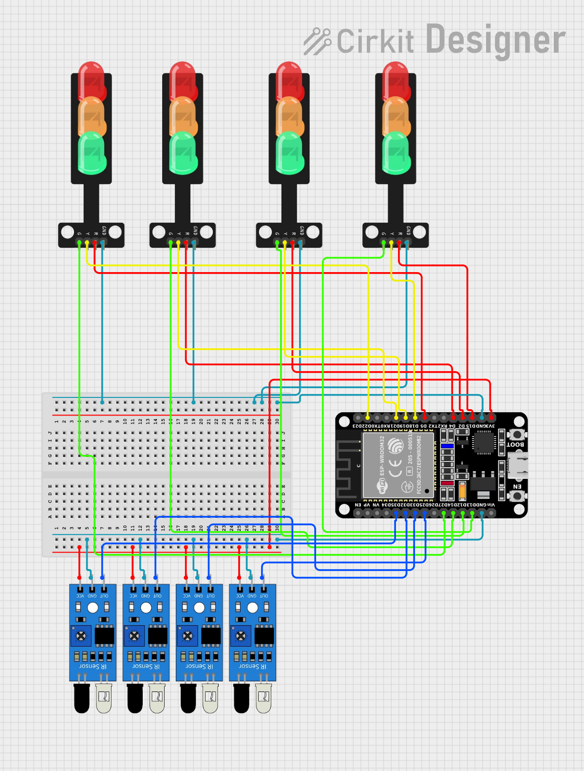
Circuit Documentation
Summary
The circuit in question is designed to interface multiple IR sensors with an ESP32 microcontroller to control a set of traffic lights. The ESP32 reads inputs from the IR sensors and drives the traffic lights accordingly. Each traffic light has three LEDs (Red, Yellow, Green) and a common ground. The IR sensors are powered by the 3.3V supply from the ESP32 and their outputs are connected to individual GPIO pins on the ESP32 for sensing.
Component List
IR Sensors
- Description: Infrared sensors used for detecting objects or motion.
- Pins:
out,gnd,vcc - Purpose: To provide input signals to the ESP32 based on the detection of objects or motion.
ESP32 (30 pin)
- Description: A microcontroller with Wi-Fi and Bluetooth capabilities.
- Pins:
EN,VP,VN,D34,D35,D32,D33,D25,D26,D27,D14,D12,D13,GND,Vin,D23,D22,TX0,RX0,D21,D19,D18,D5,TX2,RX2,D4,D2,D15,3V3 - Purpose: To process the signals from the IR sensors and control the traffic lights accordingly.
Traffic Lights
- Description: Sets of LEDs representing traffic signals.
- Pins:
Green,Yellow,Red,GND - Purpose: To display traffic signals controlled by the ESP32.
Wiring Details
IR Sensors
- VCC: Connected to the 3.3V pin on the ESP32.
- GND: Connected to the ground pin on the ESP32.
- OUT: Each sensor's output is connected to a separate GPIO pin on the ESP32 (
D35,D32,D33,D25).
ESP32 (30 pin)
- 3V3: Powers the VCC pins of all IR sensors.
- GND: Common ground for all components.
- GPIO Pins: Connected to the output pins of the IR sensors and the control pins of the traffic lights.
Traffic Lights
- Green, Yellow, Red LEDs: Each color LED of the traffic lights is connected to a specific GPIO pin on the ESP32 (
D27,D14,D12,D13for green;D22,D21,D19,D18for yellow;D5,D4,D2,D15for red). - GND: Common ground shared with the ESP32.
Documented Code
// Define traffic light control pins
int redPins[] = {15, 2, 4, 5};
int yellowPins[] = {18, 19, 21, 22};
int greenPins[] = {13, 12, 14, 27};

// Define IR sensor input pins
int irPins[] = {25, 33, 32, 35};

void setup() {
  // Initialize traffic light control pins as outputs
  for (int i = 0; i < 4; i++) {
    pinMode(redPins[i], OUTPUT);
    pinMode(yellowPins[i], OUTPUT);
    pinMode(greenPins[i], OUTPUT);
  }

  // Initialize IR sensor pins as inputs
  for (int i = 0; i < 4; i++) {
    pinMode(irPins[i], INPUT);
  }
}

void loop() {
  // Traffic light and IR sensor logic
  // ...
  // The code here controls the traffic lights based on the IR sensor inputs
  // ...
}
Note: The provided code snippet is a simplified version of the actual code. It initializes the pins and provides a structure for the main loop where the traffic light control logic should be implemented. The actual code would include the logic to read the IR sensor inputs and control the traffic lights accordingly.