
ESP8266 NodeMCU Controlled Smart Plant Watering System with Blynk App Integration
View and Edit Project In Cirkit Designer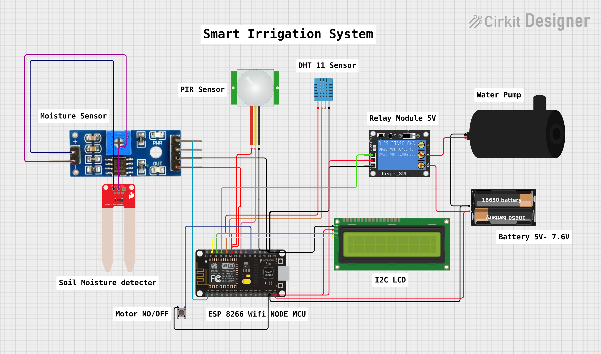
Smart Plant System Documentation
Summary
The Smart Plant System is designed to monitor and control the environmental conditions of a plant. It utilizes an ESP8266 NodeMCU microcontroller to read data from a DHT11 humidity and temperature sensor, a soil moisture sensor, and a PIR motion sensor. The system displays the collected data on an I2C LCD screen and controls a water pump through a 1-channel relay. The water pump can be activated either automatically based on the soil moisture level or manually using a pushbutton. Additionally, the system is capable of sending data to the Blynk app for remote monitoring.
Component List
ESP8266 NodeMCU
- Microcontroller with WiFi capability
- Pins: D0-D8, RX, TX, A0, RSV, SD3, SD2, SD1, CMD, SD0, CLK, EN, RST, VIN, 3V3, GND
DHT11 Humidity and Temperature Sensor
- Sensor for measuring air humidity and temperature
- Pins: VDD, DATA, NULL, GND
PIR Sensor
- Motion detection sensor
- Pins: VDD, SIG, GND
I2C LCD 16x2 Screen
- Liquid crystal display for showing text and numbers
- Pins: SCL, SDA, VCC (5V), GND, VDD, VO, RS, RW, E, D0-D7, BLA, BLK
1-Channel Relay (5V 10A)
- Electromechanical switch controlled by an electric signal
- Pins: NC, signal, C, power, NO, ground
Soil Moisture Module
- Sensor for detecting the moisture level in soil
- Pins: positive, negative, Analog, Digital, Ground, VCC
SparkFun Soil Moisture Sensor
- Another sensor for detecting soil moisture
- Pins: VCC, GND, SIG
Water Pump
- Device for moving water, controlled by the relay
- Pins: positive, negative
Battery Case
- Power source for the system
- Pins: +, -
Pushbutton
- Manual control input
- Pins: Pin 3 (out), Pin 4 (out), Pin 1 (in), Pin 2 (in)
Wiring Details
ESP8266 NodeMCU
- D1 -> I2C LCD Screen (SCL)
- D2 -> I2C LCD Screen (SDA)
- D3 -> 1-Channel Relay (signal)
- D4 -> DHT11 Sensor (DATA)
- D5 -> PIR Sensor (SIG)
- D7 -> Pushbutton (Pin 3 (out))
- 3V3 -> DHT11 Sensor (VDD), Soil Moisture Module (VCC), PIR Sensor (VDD)
- GND -> DHT11 Sensor (GND), Soil Moisture Module (Ground), 1-Channel Relay (ground), PIR Sensor (GND), I2C LCD Screen (GND), Pushbutton (Pin 1 (in)), Battery Case (-), Water Pump (negative)
- A0 -> Soil Moisture Module (Analog)
- VIN -> Battery Case (+), 1-Channel Relay (power), I2C LCD Screen (VCC (5V))
DHT11 Humidity and Temperature Sensor
- DATA -> ESP8266 NodeMCU (D4)
- VDD -> ESP8266 NodeMCU (3V3)
- GND -> ESP8266 NodeMCU (GND)
PIR Sensor
- SIG -> ESP8266 NodeMCU (D5)
- VDD -> ESP8266 NodeMCU (3V3)
- GND -> ESP8266 NodeMCU (GND)
I2C LCD 16x2 Screen
- SCL -> ESP8266 NodeMCU (D1)
- SDA -> ESP8266 NodeMCU (D2)
- VCC (5V) -> ESP8266 NodeMCU (VIN)
- GND -> ESP8266 NodeMCU (GND)
1-Channel Relay (5V 10A)
- signal -> ESP8266 NodeMCU (D3)
- power -> ESP8266 NodeMCU (VIN)
- ground -> ESP8266 NodeMCU (GND)
- NO -> Water Pump (positive)
- C -> Water Pump (positive)
Soil Moisture Module
- VCC -> ESP8266 NodeMCU (3V3)
- Ground -> ESP8266 NodeMCU (GND)
- Analog -> ESP8266 NodeMCU (A0)
- positive -> SparkFun Soil Moisture Sensor (VCC)
SparkFun Soil Moisture Sensor
- VCC -> Soil Moisture Module (positive)
- GND -> Soil Moisture Module (negative)
Water Pump
- positive -> 1-Channel Relay (NO)
- negative -> ESP8266 NodeMCU (GND)
Battery Case
-
- -> ESP8266 NodeMCU (VIN)
-
- -> ESP8266 NodeMCU (GND)
Pushbutton
- Pin 3 (out) -> ESP8266 NodeMCU (D7)
- Pin 1 (in) -> ESP8266 NodeMCU (GND)
Documented Code
/*
 * Smart Plant System with Blynk
 * This code reads data from a DHT11 sensor, a soil moisture sensor, and a PIR sensor.
 * It displays the data on an I2C LCD and controls a water pump via a relay.
 * The water pump can be activated automatically based on soil moisture levels
 * or manually using a pushbutton. Data is also sent to the Blynk app.
 */

#include <Wire.h>
#include <LiquidCrystal_I2C.h>
#include <DHT.h>
#include <BlynkSimpleEsp8266.h>

#define DHTPIN D4
#define DHTTYPE DHT11
#define SOIL_MOISTURE_PIN A0
#define PIR_PIN D5
#define RELAY_PIN D3
#define BUTTON_PIN D7

char auth[] = "YourAuthToken";
char ssid[] = "YourNetworkName";
char pass[] = "YourPassword";

DHT dht(DHTPIN, DHTTYPE);
LiquidCrystal_I2C lcd(0x27, 16, 2);

void setup() {
  pinMode(RELAY_PIN, OUTPUT);
  pinMode(BUTTON_PIN, INPUT);
  dht.begin();
  lcd.begin();
  lcd.backlight();
  lcd.print("Smart Plant");
  delay(2000);
  lcd.clear();
  Blynk.begin(auth, ssid, pass);
}

void loop() {
  Blynk.run();
  float h = dht.readHumidity();
  float t = dht.readTemperature();
  int soilMoisture = analogRead(SOIL_MOISTURE_PIN);
  int pirState = digitalRead(PIR_PIN);
  int buttonState = digitalRead(BUTTON_PIN);

  lcd.setCursor(0, 0);
  lcd.print("Temp: ");
  lcd.print(t);
  lcd.print("C");
  lcd.setCursor(0, 1);
  lcd.print("Humidity: ");
  lcd.print(h);
  lcd.print("%");
  delay(2000);

  lcd.clear();
  lcd.setCursor(0, 0);
  lcd.print("Soil: ");
  lcd.print(soilMoisture);
  lcd.setCursor(0, 1);
  lcd.print("PIR: ");
  lcd.print(pirState ? "Motion" : "No Motion");
  delay(2000);

  Blynk.virtualWrite(V1, t);
  Blynk.virtualWrite(V2, h);
  Blynk.virtualWrite(V3, soilMoisture);
  Blynk.virtualWrite(V4, pirState);

  if (soilMoisture < 300 || buttonState == HIGH) {
    digitalWrite(RELAY_PIN, HIGH);
    lcd.clear();
    lcd.setCursor(0, 0);
    lcd.print("Watering...");
    Blynk.virtualWrite(V5, 1);
    delay(5000);
    digitalWrite(RELAY_PIN, LOW);
    Blynk.virtualWrite(V5, 0);
  }
}
This code is designed to be uploaded to the ESP8266 NodeMCU microcontroller. It initializes the connected sensors and LCD, reads sensor data, and controls the relay based on soil moisture or button press. It also sends data to the Blynk app for remote monitoring.