
Arduino-Controlled Robotics Platform with L298N Motor Driver and IR/Ultrasonic Sensors
View and Edit Project In Cirkit Designer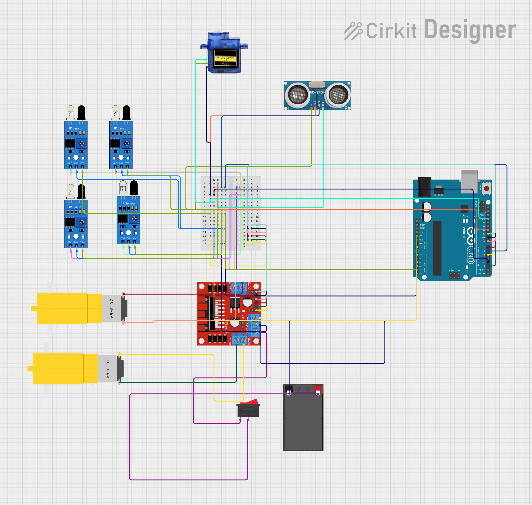
Circuit Documentation
Summary
This circuit is designed to control two DC motors using an L298N motor driver, interfaced with an Arduino UNO microcontroller. The circuit also includes multiple IR sensors for object detection, an ultrasonic sensor for distance measurement, and a micro servo for precise angular movement. A battery provides the power source, and a rocker switch is used to control the power flow. The Arduino UNO is the central processing unit, programmed to manage the inputs and outputs of the sensors, the servo, and the motor driver to perform specific tasks based on the sensor readings.
Component List
L298N DC Motor Driver
- Description: A module capable of driving two DC motors with direction and speed control.
- Pins: OUT1, OUT2, 12V, GND, 5V, OUT3, OUT4, 5V-ENA-JMP-I, 5V-ENA-JMP-O, +5V-J1, +5V-J2, ENA, IN1, IN2, IN3, IN4, ENB
IR Sensors
- Description: Sensors that detect obstacles using infrared light.
- Pins: out, gnd, vcc
Micro Servo 9G
- Description: A small servo motor capable of precise angular positioning.
- Pins: GND, +5V, PWM
Ultrasonic Sensor
- Description: A sensor that measures distance using ultrasonic waves.
- Pins: +VCC, Trigger, Echo, GND
DC Motors (Motor Amarillo Motorreductor Hobby)
- Description: Hobbyist yellow geared DC motors.
- Pins: vcc, GND
Arduino UNO
- Description: A microcontroller board based on the ATmega328P.
- Pins: UNUSED, IOREF, Reset, 3.3V, 5V, GND, Vin, A0-A5, SCL, SDA, AREF, D0-D13
Battery
- Description: The power source for the circuit.
- Pins: -, +
Rocker Switch
- Description: A switch to control the power supply to the circuit.
- Pins: 1, 2
Wiring Details
L298N DC Motor Driver
- OUT1, OUT2 connected to Motor 1
- OUT3, OUT4 connected to Motor 2
- 12V connected to Rocker Switch (pin 1)
- GND connected to Battery (-) and Arduino UNO (GND)
- 5V connected to Arduino UNO (Vin)
- ENA, IN1, IN2 connected to Arduino UNO (D5, D2, D7)
- ENB, IN3, IN4 connected to Arduino UNO (D10, D8, D9)
IR Sensors
- out connected to Arduino UNO (A0, A2, A3, A1)
- gnd connected to Arduino UNO (GND)
- vcc connected to Arduino UNO (5V)
Micro Servo 9G
- GND connected to Arduino UNO (GND)
- +5V connected to Arduino UNO (5V)
- PWM connected to Arduino UNO (D3)
Ultrasonic Sensor
- +VCC connected to Arduino UNO (5V)
- Trigger connected to Arduino UNO (D11)
- Echo connected to Arduino UNO (D6)
- GND connected to Arduino UNO (GND)
DC Motors (Motor Amarillo Motorreductor Hobby)
- vcc and GND connected to L298N DC Motor Driver (OUT1, OUT2, OUT3, OUT4)
Battery
-
- connected to Rocker Switch (pin 2)
-
- connected to L298N DC Motor Driver (GND)
Rocker Switch
- Pin 1 connected to L298N DC Motor Driver (12V)
- Pin 2 connected to Battery (+)
Documented Code
void setup() {
  // put your setup code here, to run once:

}

void loop() {
  // put your main code here, to run repeatedly:

}
The provided code is a template with empty setup() and loop() functions, which are the entry points for Arduino sketches. The setup() function is called once when the sketch starts and is used for initializing settings, while the loop() function runs repeatedly, allowing the microcontroller to perform operations based on sensor inputs and control outputs like motors and servos. The actual implementation details would be added to these functions based on the specific requirements of the circuit's operation.