
Arduino UNO Obstacle-Avoiding Robot with Ultrasonic Sensor and RGB LED
View and Edit Project In Cirkit Designer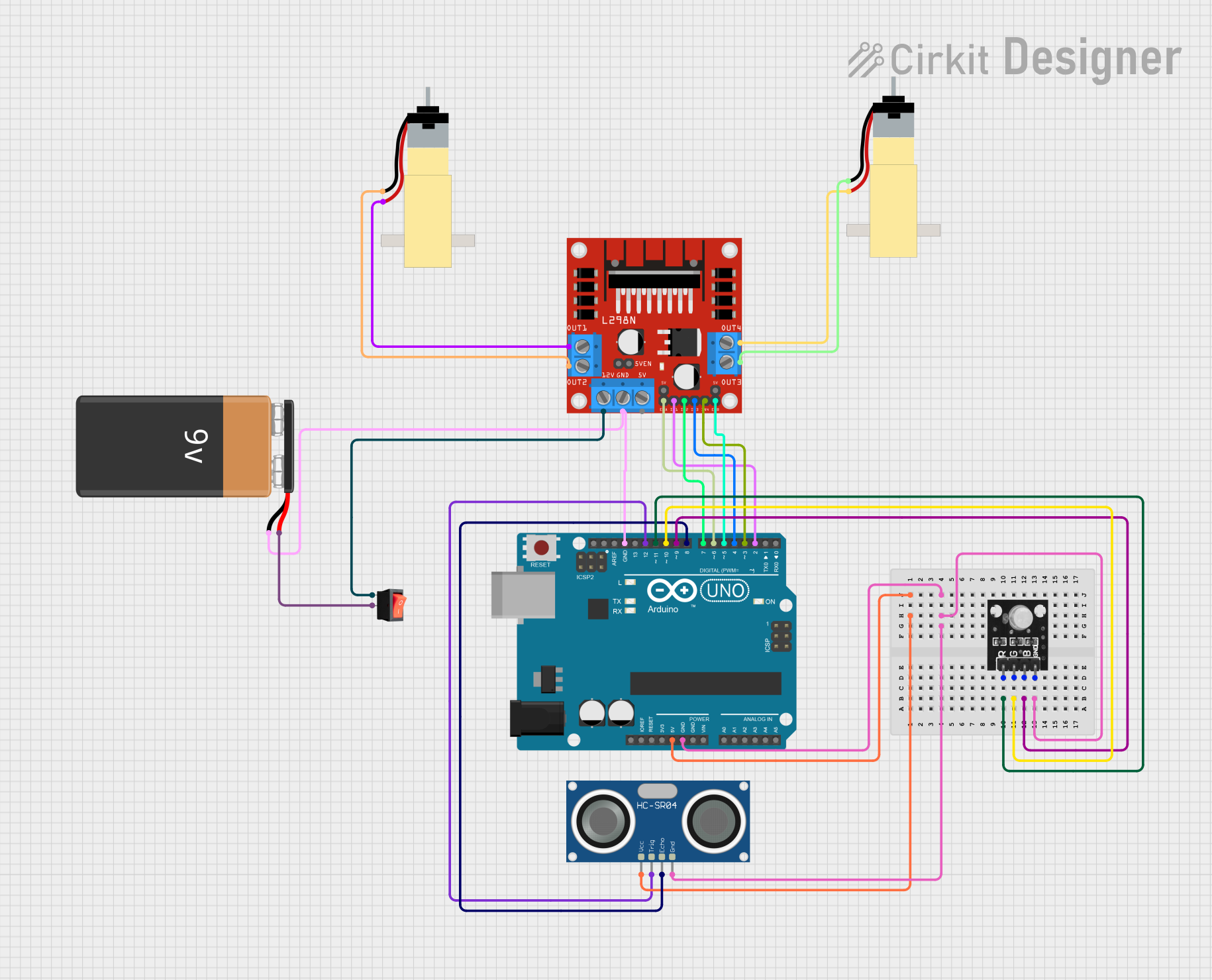
Circuit Documentation
Summary
This circuit is designed to control a robot that avoids obstacles using an ultrasonic sensor and two gear motors. The robot is controlled by an Arduino UNO microcontroller, which also drives an RGB LED module to indicate the robot's status. The L298N DC motor driver is used to control the motors, and a rocker switch is used to power the circuit from a 9V battery.
Component List
Arduino UNO
- Description: Microcontroller board based on the ATmega328P.
- Pins: UNUSED, IOREF, Reset, 3.3V, 5V, GND, Vin, A0, A1, A2, A3, A4, A5, SCL, SDA, AREF, D13, D12, D11, D10, D9, D8, D7, D6, D5, D4, D3, D2, D1, D0
L298N DC Motor Driver
- Description: Dual H-Bridge motor driver module.
- Pins: OUT1, OUT2, 12V, GND, 5V, OUT3, OUT4, 5V-ENA-JMP-I, 5V-ENA-JMP-O, +5V-J1, +5V-J2, ENA, IN1, IN2, IN3, IN4, ENB
HC-SR04 Ultrasonic Sensor
- Description: Ultrasonic distance sensor.
- Pins: VCC, TRIG, ECHO, GND
Hobby Gearmotor with 48:1 Gearbox
- Description: Small DC motor with a 48:1 gearbox.
- Pins: pin 1, pin 2
Rocker Switch
- Description: Simple on/off switch.
- Pins: output, input
9V Battery
- Description: Standard 9V battery for powering the circuit.
- Pins: -, +
RGB LED Module
- Description: RGB LED module for indicating status.
- Pins: +VCC Red, +VCC Green, +VCC Blue, GND
Wiring Details
Arduino UNO
- 5V connected to VCC of HC-SR04 Ultrasonic Sensor.
- GND connected to GND of HC-SR04 Ultrasonic Sensor, GND of RGB LED Module, and GND of L298N DC Motor Driver.
- D11 connected to +VCC Red of RGB LED Module.
- D10 connected to +VCC Green of RGB LED Module.
- D9 connected to +VCC Blue of RGB LED Module.
- D12 connected to TRIG of HC-SR04 Ultrasonic Sensor.
- D8 connected to ECHO of HC-SR04 Ultrasonic Sensor.
- D7 connected to IN2 of L298N DC Motor Driver.
- D6 connected to ENA of L298N DC Motor Driver.
- D5 connected to ENB of L298N DC Motor Driver.
- D4 connected to IN3 of L298N DC Motor Driver.
- D3 connected to IN4 of L298N DC Motor Driver.
- D2 connected to IN1 of L298N DC Motor Driver.
L298N DC Motor Driver
- GND connected to - of 9V Battery and GND of Arduino UNO.
- OUT1 connected to pin 2 of Hobby Gearmotor with 48:1 Gearbox.
- OUT2 connected to pin 1 of Hobby Gearmotor with 48:1 Gearbox.
- OUT3 connected to pin 1 of Hobby Gearmotor with 48:1 Gearbox.
- OUT4 connected to pin 2 of Hobby Gearmotor with 48:1 Gearbox.
- 12V connected to input of Rocker Switch.
HC-SR04 Ultrasonic Sensor
- VCC connected to 5V of Arduino UNO.
- GND connected to GND of Arduino UNO.
- TRIG connected to D12 of Arduino UNO.
- ECHO connected to D8 of Arduino UNO.
Hobby Gearmotor with 48:1 Gearbox
- pin 2 connected to OUT1 of L298N DC Motor Driver.
- pin 1 connected to OUT2 of L298N DC Motor Driver.
- pin 1 connected to OUT3 of L298N DC Motor Driver.
- pin 2 connected to OUT4 of L298N DC Motor Driver.
Rocker Switch
- input connected to 12V of L298N DC Motor Driver.
- output connected to + of 9V Battery.
9V Battery
- - connected to GND of L298N DC Motor Driver.
- + connected to output of Rocker Switch.
RGB LED Module
- GND connected to GND of Arduino UNO.
- +VCC Red connected to D11 of Arduino UNO.
- +VCC Green connected to D10 of Arduino UNO.
- +VCC Blue connected to D9 of Arduino UNO.
Documented Code
Arduino UNO Code
/*
 * Robot esquiva obstaculos
 * Este código controla un robot que esquiva obstáculos usando un sensor
 * ultrasónico y dos motores de engranajes. También utiliza un módulo LED RGB
 * para indicar el estado del robot.
 */

// Pines de control de velocidad de los motores
int VelocidadMotor1 = 6;
int VelocidadMotor2 = 5;

// Pines de control de dirección de los motores
int Motor1A = 2;
int Motor1B = 7;
int Motor2C = 4;
int Motor2D = 3;

// Pines del sensor ultrasónico
#define PIN_TRIG 12
#define PIN_ECHO 8

// Pines del módulo LED RGB
int ledRed = 11;
int ledGreen = 10;
int ledBlue = 9;

long duration, distancia;

void setup() {
  Serial.begin(9600);

  // Configuración del sensor ultrasónico
  pinMode(PIN_TRIG, OUTPUT);
  pinMode(PIN_ECHO, INPUT);

  // Configuración de los pines de los motores
  pinMode(Motor1A, OUTPUT);
  pinMode(Motor1B, OUTPUT);
  pinMode(Motor2C, OUTPUT);
  pinMode(Motor2D, OUTPUT);
  pinMode(VelocidadMotor1, OUTPUT);
  pinMode(VelocidadMotor2, OUTPUT);

  // Configuración de los pines del LED RGB
  pinMode(ledRed, OUTPUT);
  pinMode(ledGreen, OUTPUT);
  pinMode(ledBlue, OUTPUT);

  // Configuración inicial de los motores
  analogWrite(VelocidadMotor1, 150);
  analogWrite(VelocidadMotor2, 150);
  digitalWrite(Motor1A, LOW);
  digitalWrite(Motor1B, LOW);
  digitalWrite(Motor2C, LOW);
  digitalWrite(Motor2D, LOW);
}

void loop() {
  // Medición de distancia con el sensor ultrasónico
  digitalWrite(PIN_TRIG, LOW);
  delayMicroseconds(5);
  digitalWrite(PIN_TRIG, HIGH);
  delayMicroseconds(10);
  digitalWrite(PIN_TRIG, LOW);
  duration = pulseIn(PIN_ECHO, HIGH);
  distancia = (duration / 2) / 29.1;
  Serial.print("Distancia al objeto: ");
  Serial.print(distancia);
  Serial.println(" cm");

  if (distancia > 10) {
    // Avanzar
    digitalWrite(Motor1A, HIGH);
    digitalWrite(Motor1B, LOW);
    digitalWrite(Motor2C, HIGH);
    digitalWrite(Motor2D, LOW);
    setLEDColor(0, 255, 0); // Verde
  } else {
    // Detener y girar
    digitalWrite(Motor1A, LOW);
    digitalWrite(Motor1B, LOW);
    digitalWrite(Motor2C, LOW);
    digitalWrite(Motor2D, LOW);
    delay(500);
    digitalWrite(Motor1A, LOW);
    digitalWrite(Motor1B, HIGH);
    digitalWrite(Motor2C, HIGH);
    digitalWrite(Motor2D, LOW);
    setLEDColor(255, 0, 0); // Rojo
    delay(1000);
  }
}

void setLEDColor(int red, int green, int blue) {
  analogWrite(ledRed, red);
  analogWrite(ledGreen, green);
  analogWrite(ledBlue, blue);
}
L298N DC Motor Driver Code
void setup() {
  // put your setup code here, to run once:

}

void loop() {
  // put your main code here, to run repeatedly