
ESP32 and Multiplexer-Based Multi-Channel Current Monitoring System
View and Edit Project In Cirkit Designer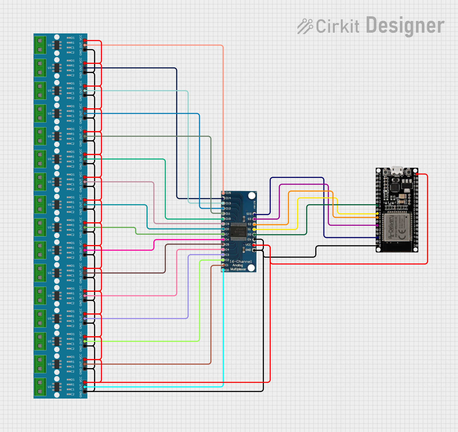
Circuit Documentation
Summary
This circuit consists of an ESP32 microcontroller, a 16-channel analog multiplexer, and multiple ACS712 current sensors. The ESP32 controls the multiplexer to select different current sensors, allowing it to read current measurements from multiple channels. The multiplexer and current sensors are powered by the ESP32.
Component List
16 Channel Analog Multiplexer Bob
- Description: A multiplexer that allows one of 16 analog inputs to be selected and routed to a single output.
- Pins: GND, VCC, EN, S0, S1, S2, S3, SIG, C0, C1, C2, C3, C4, C5, C6, C7, C8, C9, C10, C11, C12, C13, C14, C15
ESP32 38 PINS
- Description: A powerful microcontroller with Wi-Fi and Bluetooth capabilities.
- Pins: GND, G23, G22, TXD, RXD, G21, G19, G18, G5, G17, G16, G4, G0, G2, G15, SDI, SD0, CLK, 3V3, EN, SP, SN, G34, G35, G32, 33, G25, G26, G27, G14, G12, G13, SD2, SD3, 5V
ACS712 Current Sensor 5A 20A 30A
- Description: A current sensor that provides an analog voltage output proportional to the current passing through it.
- Pins: 1, 2, GND, OUT, VCC
Wiring Details
16 Channel Analog Multiplexer Bob
- GND: Connected to GND of ESP32 and GND of all ACS712 sensors.
- VCC: Connected to 5V of ESP32 and VCC of all ACS712 sensors.
- EN: Connected to GND.
- S0: Connected to G17 of ESP32.
- S1: Connected to G18 of ESP32.
- S2: Connected to G19 of ESP32.
- S3: Connected to G21 of ESP32.
- SIG: Connected to G22 of ESP32.
- C0: Connected to OUT of ACS712 sensor 1.
- C1: Connected to OUT of ACS712 sensor 2.
- C2: Connected to OUT of ACS712 sensor 3.
- C3: Connected to OUT of ACS712 sensor 4.
- C4: Connected to OUT of ACS712 sensor 5.
- C5: Connected to OUT of ACS712 sensor 6.
- C6: Connected to OUT of ACS712 sensor 7.
- C7: Connected to OUT of ACS712 sensor 8.
- C8: Connected to OUT of ACS712 sensor 9.
- C9: Connected to OUT of ACS712 sensor 10.
- C10: Connected to OUT of ACS712 sensor 11.
- C11: Connected to OUT of ACS712 sensor 12.
- C12: Connected to OUT of ACS712 sensor 13.
- C13: Connected to OUT of ACS712 sensor 14.
- C14: Connected to OUT of ACS712 sensor 15.
- C15: Connected to OUT of ACS712 sensor 16.
ESP32 38 PINS
- GND: Connected to GND of multiplexer and GND of all ACS712 sensors.
- 5V: Connected to VCC of multiplexer and VCC of all ACS712 sensors.
- G17: Connected to S0 of multiplexer.
- G18: Connected to S1 of multiplexer.
- G19: Connected to S2 of multiplexer.
- G21: Connected to S3 of multiplexer.
- G22: Connected to SIG of multiplexer.
ACS712 Current Sensor 5A 20A 30A
- GND: Connected to GND of ESP32 and multiplexer.
- VCC: Connected to 5V of ESP32 and multiplexer.
- OUT: Connected to respective C0 to C15 pins of the multiplexer.
Code
No code provided.