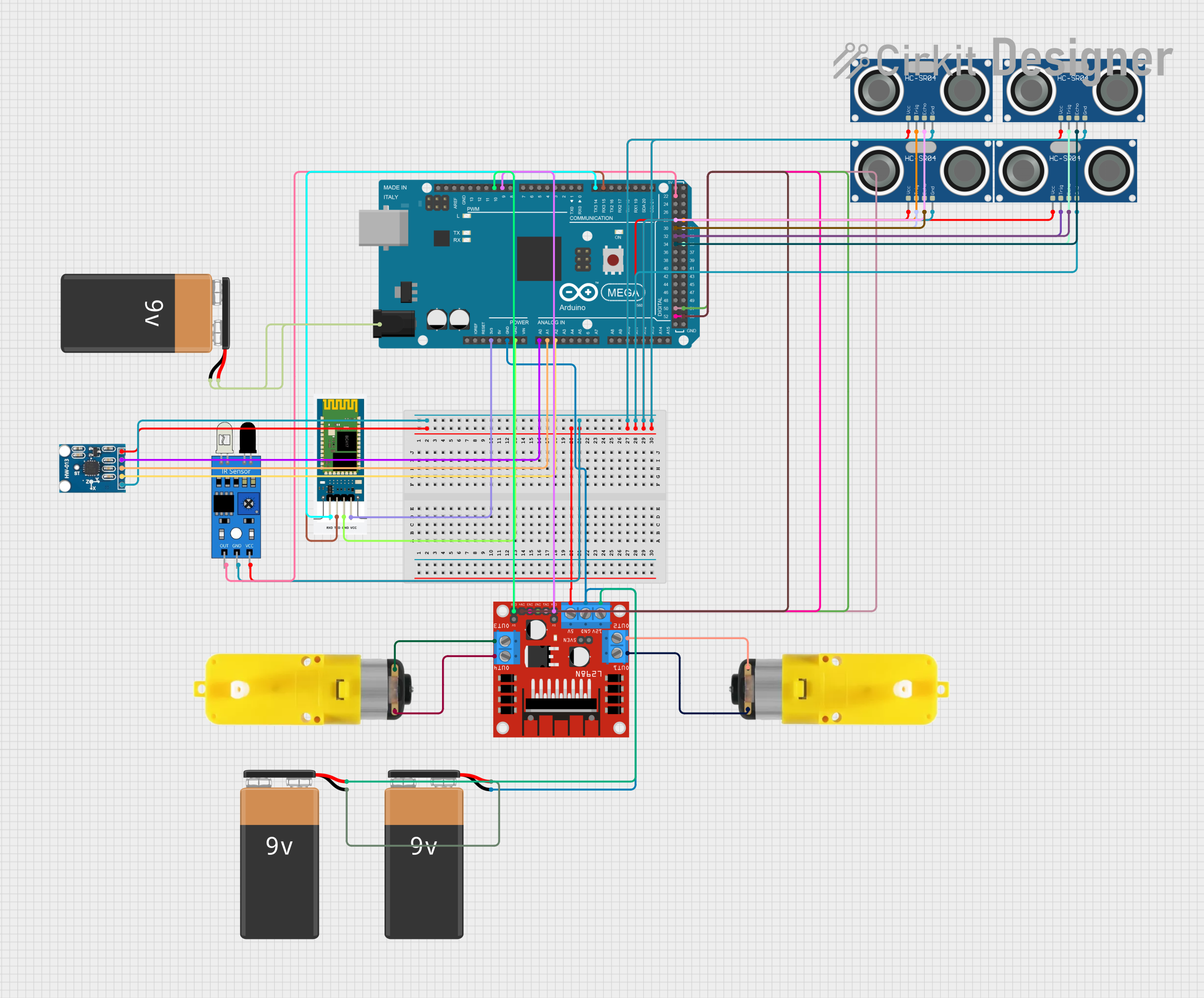
Arduino Mega 2560-Based Battery-Powered Robotic System with Ultrasonic and IR Sensors
Circuit Documentation
Summary
This document provides a detailed overview of a circuit that includes an Arduino Mega 2560 microcontroller, multiple sensors (ultrasonic, IR, and accelerometer), a motor driver, motors, and a Bluetooth module. The circuit is powered by multiple 9V batteries. The Arduino Mega 2560 is the central controller, interfacing with various sensors and actuators to perform specific tasks.
Component List
Arduino Mega 2560
- Description: A microcontroller board based on the ATmega2560.
- Pins: IOREF, RESET, 3V3, 5V, GND, VIN, A0-A15, D0-D53, AREF, SDA, SCL
9V Battery
- Description: Standard 9V battery for power supply.
- Pins: +, -
HC-SR04 Ultrasonic Sensor
- Description: Ultrasonic distance sensor.
- Pins: VCC, TRIG, ECHO, GND
IR Sensor
- Description: Infrared sensor for object detection.
- Pins: out, gnd, vcc
Motor with Reducer
- Description: DC motor with a gear reducer.
- Pins: 3 - 6 VCC, GND
L298N DC Motor Driver
- Description: Dual H-Bridge motor driver.
- Pins: OUT1, OUT2, 12V, GND, 5V, OUT3, OUT4, 5V-ENA-JMP-I, 5V-ENA-JMP-O, +5V-J1, +5V-J2, ENA, IN1, IN2, IN3, IN4, ENB
HC-06 Bluetooth Module
- Description: Bluetooth module for wireless communication.
- Pins: RXD, TXD, GND, VCC
AITrip ADXL335 GY-61
- Description: 3-axis accelerometer.
- Pins: GND, Z-Out, Y-Out, X-Out, VCC
Wiring Details
Arduino Mega 2560
- 3V3: Connected to VCC of HC-06 Bluetooth Module.
- GND: Connected to GND of L298N DC Motor Driver, GND of HC-06 Bluetooth Module, and - of 9V Battery.
- A0: Connected to X-Out of AITrip ADXL335 GY-61.
- A1: Connected to Y-Out of AITrip ADXL335 GY-61.
- A2: Connected to Z-Out of AITrip ADXL335 GY-61.
- D15/RX3: Connected to TXD of HC-06 Bluetooth Module.
- D14/TX3: Connected to RXD of HC-06 Bluetooth Module.
- D9 PWM: Connected to ENA of L298N DC Motor Driver.
- D10 PWM: Connected to ENB of L298N DC Motor Driver.
- D52: Connected to IN3 of L298N DC Motor Driver.
- D50: Connected to IN1 of L298N DC Motor Driver.
- D34: Connected to ECHO of HC-SR04 Ultrasonic Sensor.
- D32: Connected to ECHO of another HC-SR04 Ultrasonic Sensor.
- D30: Connected to ECHO of another HC-SR04 Ultrasonic Sensor.
- D28: Connected to ECHO of another HC-SR04 Ultrasonic Sensor.
- D22: Connected to out of IR Sensor.
- D53: Connected to IN4 of L298N DC Motor Driver.
- D51: Connected to IN2 of L298N DC Motor Driver.
- D35: Connected to TRIG of HC-SR04 Ultrasonic Sensor.
- D33: Connected to TRIG of another HC-SR04 Ultrasonic Sensor.
- D31: Connected to TRIG of another HC-SR04 Ultrasonic Sensor.
- D29: Connected to TRIG of another HC-SR04 Ultrasonic Sensor.
- 6swdw: Connected to - and + of 9V Battery.
9V Battery
- -: Connected to GND of Arduino Mega 2560 and another 9V Battery.
- +: Connected to another 9V Battery and 12V of L298N DC Motor Driver.
HC-SR04 Ultrasonic Sensor
- VCC: Connected to 5V of L298N DC Motor Driver.
- GND: Connected to GND of AITrip ADXL335 GY-61.
- TRIG: Connected to D35, D33, D31, and D29 of Arduino Mega 2560.
- ECHO: Connected to D34, D32, D30, and D28 of Arduino Mega 2560.
IR Sensor
- out: Connected to D22 of Arduino Mega 2560.
- gnd: Connected to GND of AITrip ADXL335 GY-61.
- vcc: Connected to 5V of L298N DC Motor Driver.
Motor with Reducer
- 3 - 6 VCC: Connected to OUT3 and OUT1 of L298N DC Motor Driver.
- GND: Connected to OUT4 and OUT2 of L298N DC Motor Driver.
L298N DC Motor Driver
- 5V: Connected to VCC of AITrip ADXL335 GY-61 and vcc of IR Sensor.
- GND: Connected to GND of Arduino Mega 2560.
- 12V: Connected to + of 9V Battery.
- OUT1: Connected to 3 - 6 VCC of Motor with Reducer.
- OUT2: Connected to GND of Motor with Reducer.
- OUT3: Connected to 3 - 6 VCC of another Motor with Reducer.
- OUT4: Connected to GND of another Motor with Reducer.
- ENA: Connected to D9 PWM of Arduino Mega 2560.
- ENB: Connected to D10 PWM of Arduino Mega 2560.
- IN1: Connected to D50 of Arduino Mega 2560.
- IN2: Connected to D51 of Arduino Mega 2560.
- IN3: Connected to D52 of Arduino Mega 2560.
- IN4: Connected to D53 of Arduino Mega 2560.
HC-06 Bluetooth Module
- RXD: Connected to D14/TX3 of Arduino Mega 2560.
- TXD: Connected to D15/RX3 of Arduino Mega 2560.
- GND: Connected to GND of Arduino Mega 2560.
- VCC: Connected to 3V3 of Arduino Mega 2560.
AITrip ADXL335 GY-61
- GND: Connected to GND of IR Sensor.
- Z-Out: Connected to A2 of Arduino Mega 2560.
- Y-Out: Connected to A1 of Arduino Mega 2560.
- X-Out: Connected to A0 of Arduino Mega 2560.
- VCC: Connected to 5V of L298N DC Motor Driver.
Documented Code
Arduino Mega 2560 Code
void setup() {
  // put your setup code here, to run once:

}

void loop() {
  // put your main code here, to run repeatedly:

}
This code is a basic template for the Arduino Mega 2560. The setup() function is used to initialize any settings or configurations, and the loop() function contains the main logic that runs repeatedly. You can add your specific logic to interact with the connected sensors and actuators in these functions.