Cirkit Designer
Your all-in-one circuit design IDE
Home /
Project Documentation
Arduino Mega 2560-Based Smart Water Quality Monitoring System with Wi-Fi Connectivity

Circuit Documentation
Summary
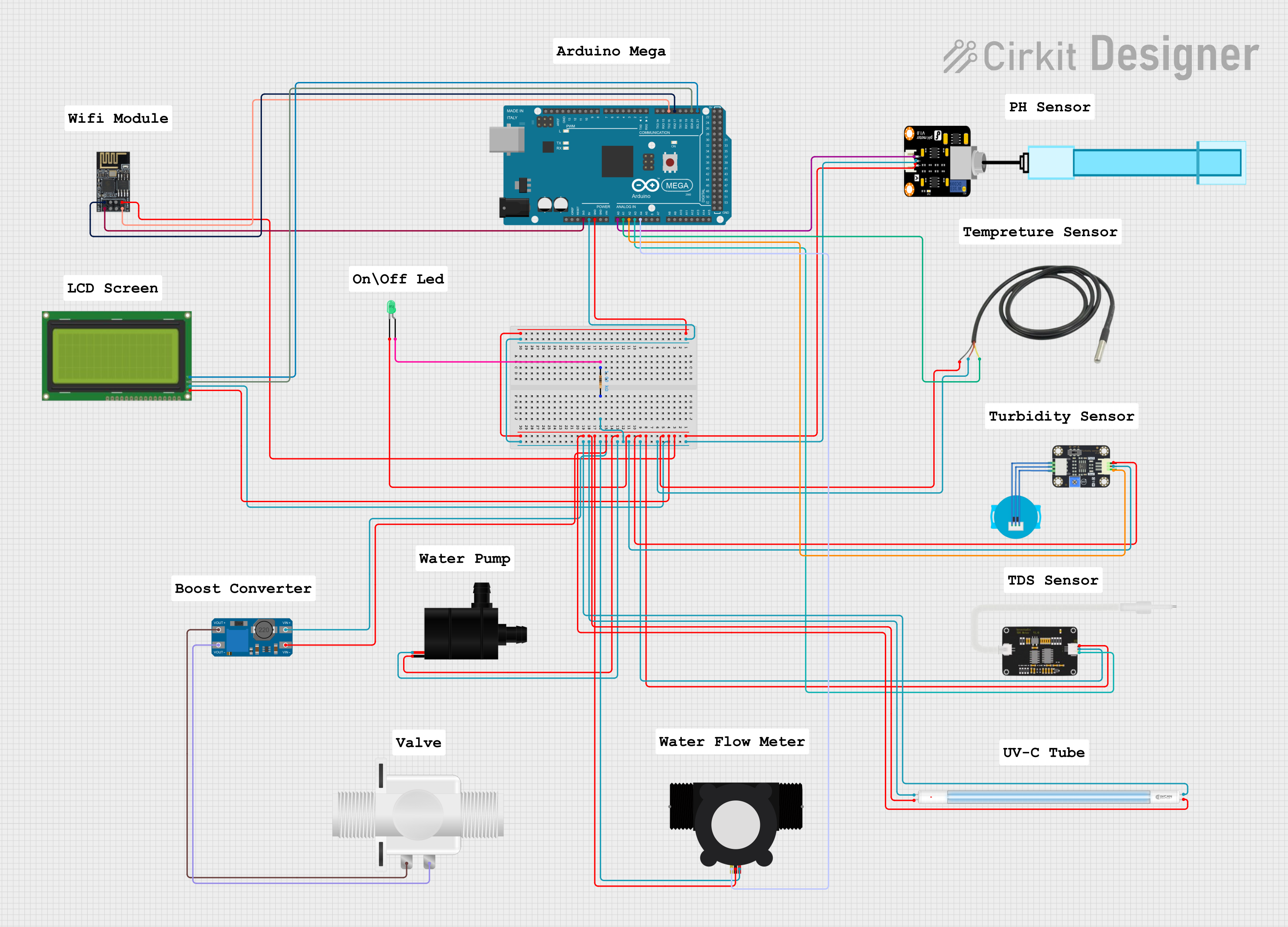
This circuit is designed to interface various sensors and actuators with an Arduino Mega 2560 microcontroller. The components include a pH meter, temperature sensor, turbidity sensor, TDS sensor, water flow meter, LCD display, WiFi module, water pump, solenoid valve, UV-C tube, and an LED. The circuit is powered by the Arduino Mega 2560, which also handles data acquisition and control tasks.
Component List
Arduino Mega 2560
- Description: A microcontroller board based on the ATmega2560.
- Pins: IOREF, RESET, 3V3, 5V, GND, VIN, A0-A15, D0-D53, PWM pins, AREF, SDA, SCL.
PH Meter
- Description: Measures the pH level of a solution.
- Pins: Signal, VCC, GND.
Temperature Sensor
- Description: Measures temperature.
- Pins: Temp GND Black, Temp VDD Red, Temp DQ Data Yellow.
LED: Two Pin (green)
- Description: A green LED.
- Pins: Cathode, Anode.
Resistor
- Description: A resistor with a resistance of 1000 Ohms.
- Pins: Pin1, Pin2.
Wifi module ESP8266-01
- Description: A WiFi module for wireless communication.
- Pins: RX, GPIO0, GPIO2, GND, +3V3, Reset, CH-PD Chip power down, TX.
MT3608
- Description: A DC-DC step-up converter.
- Pins: VOUT+, VIN+, VOUT-, VIN-.
Lcd 20x4 i2c
- Description: A 20x4 character LCD display with I2C interface.
- Pins: GND, 5V, SCA, SCL.
Plastic Solenoid Valve
- Description: A solenoid valve for controlling fluid flow.
- Pins: Pin1, Pin2.
Water Pump
- Description: A pump for moving water.
- Pins: VCC, GND.
TDS Sensor 2
- Description: Measures Total Dissolved Solids in water.
- Pins: AIn, GND, 5V.
Turbidity Sensor
- Description: Measures the turbidity (cloudiness) of water.
- Pins: OUT, VCC, GND.
YF-S201 Water Flow Meter
- Description: Measures the flow rate of water.
- Pins: SIG, GND, VCC.
UV-C Tube
- Description: A UV-C light tube for sterilization.
- Pins: +, -.
Wiring Details
Arduino Mega 2560
- 5V: Connected to VCC of PH Meter, 5V of Lcd 20x4 i2c, Temp VDD Red of Temperature Sensor, 5V of TDS Sensor 2, VCC of Turbidity Sensor, VCC of Water Pump, VIN+ of MT3608, VCC of YF-S201 Water Flow Meter, + of UV-C Tube.
- GND: Connected to GND of PH Meter, GND of Wifi module ESP8266-01, GND of Lcd 20x4 i2c, Temp GND Black of Temperature Sensor, GND of TDS Sensor 2, GND of Turbidity Sensor, Cathode of LED: Two Pin (green), GND of Water Pump, VIN- of MT3608, GND of YF-S201 Water Flow Meter, - of UV-C Tube.
- 3V3: Connected to +3V3 of Wifi module ESP8266-01.
- A0: Connected to Signal of PH Meter.
- A1: Connected to Temp DQ Data Yellow of Temperature Sensor.
- A2: Connected to OUT of Turbidity Sensor.
- A3: Connected to AIn of TDS Sensor 2.
- A4: Connected to SIG of YF-S201 Water Flow Meter.
- D21/SCL: Connected to SCL of Lcd 20x4 i2c.
- D20/SDA: Connected to SCA of Lcd 20x4 i2c.
- D17 PWM/RX2: Connected to RX of Wifi module ESP8266-01.
- D16 PWM/TX2: Connected to TX of Wifi module ESP8266-01.
PH Meter
- Signal: Connected to A0 of Arduino Mega 2560.
- VCC: Connected to 5V of Arduino Mega 2560.
- GND: Connected to GND of Arduino Mega 2560.
Temperature Sensor
- Temp GND Black: Connected to GND of Arduino Mega 2560.
- Temp VDD Red: Connected to 5V of Arduino Mega 2560.
- Temp DQ Data Yellow: Connected to A1 of Arduino Mega 2560.
LED: Two Pin (green)
- Anode: Connected to Pin1 of Resistor.
- Cathode: Connected to GND of Arduino Mega 2560.
Resistor
- Pin1: Connected to Anode of LED: Two Pin (green).
- Pin2: Connected to VCC of PH Meter, 5V of Lcd 20x4 i2c, Temp VDD Red of Temperature Sensor, 5V of TDS Sensor 2, VCC of Turbidity Sensor, VCC of Water Pump, VIN+ of MT3608, VCC of YF-S201 Water Flow Meter, + of UV-C Tube.
Wifi module ESP8266-01
- RX: Connected to D17 PWM/RX2 of Arduino Mega 2560.
- GND: Connected to GND of Arduino Mega 2560.
- +3V3: Connected to 3V3 of Arduino Mega 2560.
- TX: Connected to D16 PWM/TX2 of Arduino Mega 2560.
MT3608
- VIN+: Connected to 5V of Arduino Mega 2560.
- VIN-: Connected to GND of Arduino Mega 2560.
- VOUT+: Connected to Pin1 of Plastic Solenoid Valve.
- VOUT-: Connected to Pin2 of Plastic Solenoid Valve.
Lcd 20x4 i2c
- GND: Connected to GND of Arduino Mega 2560.
- 5V: Connected to 5V of Arduino Mega 2560.
- SCA: Connected to D20/SDA of Arduino Mega 2560.
- SCL: Connected to D21/SCL of Arduino Mega 2560.
Plastic Solenoid Valve
- Pin1: Connected to VOUT+ of MT3608.
- Pin2: Connected to VOUT- of MT3608.
Water Pump
- VCC: Connected to 5V of Arduino Mega 2560.
- GND: Connected to GND of Arduino Mega 2560.
TDS Sensor 2
- AIn: Connected to A3 of Arduino Mega 2560.
- GND: Connected to GND of Arduino Mega 2560.
- 5V: Connected to 5V of Arduino Mega 2560.
Turbidity Sensor
- OUT: Connected to A2 of Arduino Mega 2560.
- VCC: Connected to 5V of Arduino Mega 2560.
- GND: Connected to GND of Arduino Mega 2560.
YF-S201 Water Flow Meter
- SIG: Connected to A4 of Arduino Mega 2560.
- GND: Connected to GND of Arduino Mega 2560.
- VCC: Connected to 5V of Arduino Mega 2560.
UV-C Tube
- +: Connected to 5V of Arduino Mega 2560.
- -: Connected to GND of Arduino Mega 2560.
Code Documentation
Arduino Mega 2560 Code
sketch.ino
void setup() {
  // put your setup code here, to run once:

}

void loop() {
  // put your main code here, to run repeatedly:

}
documentation.txt