
Raspberry Pi-Based Multi-Sensor Monitoring System with Relay Control
View and Edit Project In Cirkit Designer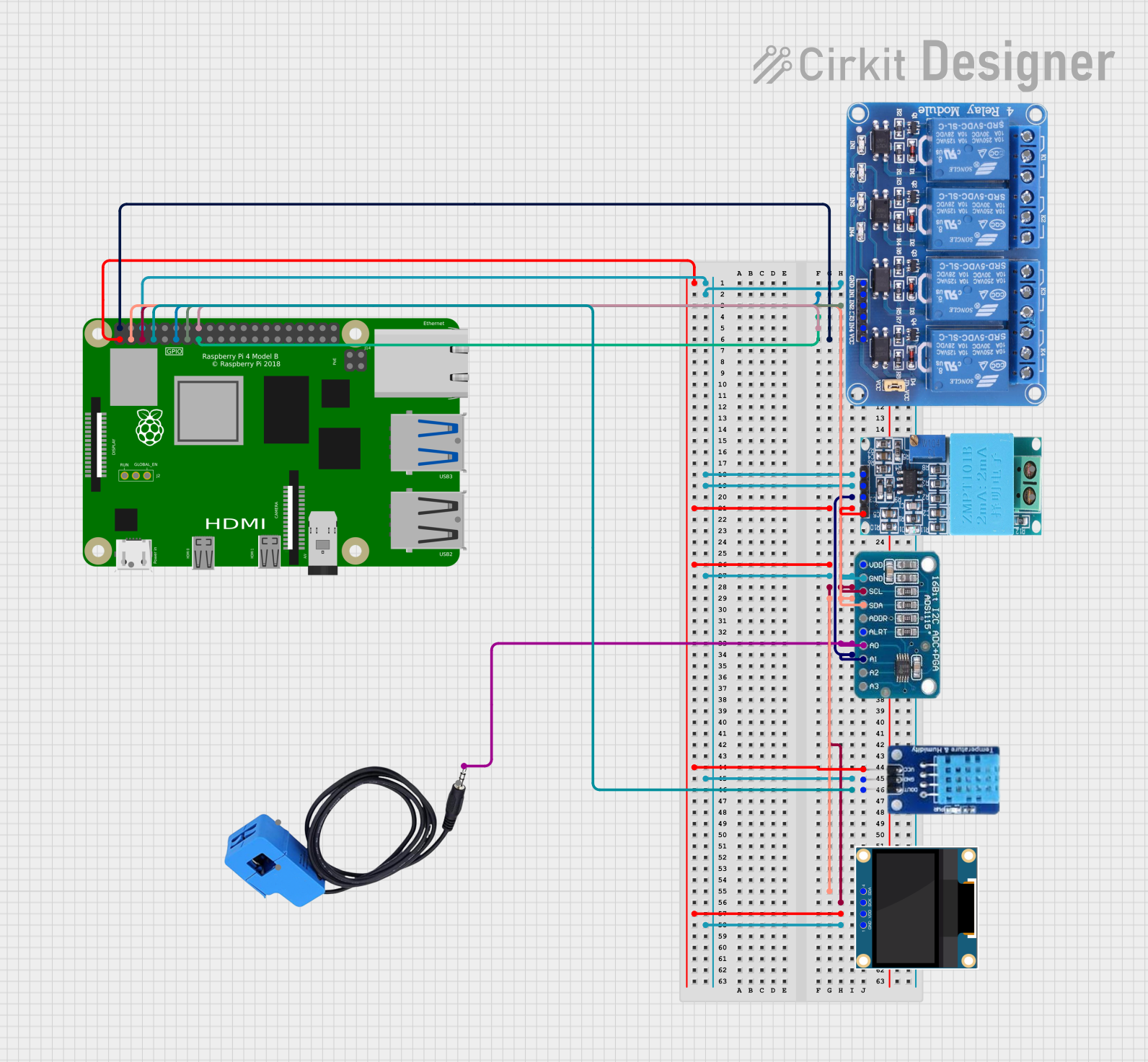
Circuit Documentation
Summary
This circuit is designed to interface a variety of sensors and devices with a Raspberry Pi 4B, which acts as the central processing unit. The circuit includes a ZMPT101B module for voltage sensing, an ADS1115 for precision analog-to-digital conversion, a 0.96" OLED display for data output, a current sensor for current measurement, a 4-channel 5V relay module for controlling high power devices, and a DHT11 sensor for measuring temperature and humidity. The Raspberry Pi 4B is responsible for reading data from the sensors, processing it, and controlling the relay module based on the processed data. The circuit is powered by the Raspberry Pi's 3.3V and 5V pins and includes a common ground for all components.
Component List
ZMPT101B
- Description: Voltage sensor module for AC voltage.
- Pins: OUT, GND, VCC, NEUTRO, FASE
ADS1115
- Description: 16-bit precision analog-to-digital converter (ADC) with I2C interface.
- Pins: VDD, GND, SCL, SDA, ADDR, ALRT, A0, A1, A2, A3
0.96" OLED
- Description: Small OLED display for visual data output.
- Pins: GND, VDD, SCK, SDA
Current Sensor
- Description: Sensor for measuring electrical current.
- Pins: Out, Burden, In_current, Out_current
Relay 4 Channel 5v
- Description: 4-channel relay module for controlling high power devices.
- Pins: GND, IN1, IN2, IN3, IN4, VCC, COM1, COM2, COM3, COM4, NO1, NO2, NO3, NO4, NC1, NC2, NC3, NC4
Raspberry Pi 4B
- Description: Microcomputer used as the main controller.
- Pins: 3V3, 5V, GPIO2, GPIO3, GND, GPIO4, GPIO14, GPIO15, GPIO17, GPIO18, GPIO27, GPIO22, GPIO23, GPIO24, GPIO10, GPIO9, GPIO25, GPIO11, GPIO8, GPIO7, ID_SD, GPIO5, GPIO6, GPIO12, GPIO13, GPIO19, GPIO16, GPIO26, GPIO20, GPIO21, ID_SC, TR01_TAP, TR00_TAP, TR03_TAP, TR02_TAP, RUN, GLOBAL_EN
DHT11
- Description: Sensor for measuring temperature and humidity.
- Pins: DATA, GND, VCC
Wiring Details
ZMPT101B
- OUT connected to ADS1115 A1
- GND connected to common ground
- VCC connected to Raspberry Pi 4B 3V3
ADS1115
- VDD connected to Raspberry Pi 4B 3V3
- GND connected to common ground
- SCL connected to Raspberry Pi 4B GPIO3
- SDA connected to Raspberry Pi 4B GPIO2
- A0 connected to Current Sensor Out
- A1 connected to ZMPT101B OUT
0.96" OLED
- GND connected to common ground
- VDD connected to Raspberry Pi 4B 3V3
- SCK connected to Raspberry Pi 4B GPIO3
- SDA connected to Raspberry Pi 4B GPIO2
Current Sensor
- Out connected to ADS1115 A0
Relay 4 Channel 5v
- GND connected to common ground
- IN1 connected to Raspberry Pi 4B GPIO17
- IN2 connected to Raspberry Pi 4B GPIO27
- IN3 connected to Raspberry Pi 4B GPIO22
- IN4 connected to Raspberry Pi 4B GPIO23
- VCC connected to Raspberry Pi 4B 5V
Raspberry Pi 4B
- 3V3 connected to ZMPT101B VCC, ADS1115 VDD, 0.96" OLED VDD, DHT11 VCC
- 5V connected to Relay 4 Channel 5v VCC
- GPIO2 connected to 0.96" OLED SDA, ADS1115 SDA
- GPIO3 connected to 0.96" OLED SCK, ADS1115 SCL
- GPIO4 connected to DHT11 DATA
- GPIO17 connected to Relay 4 Channel 5v IN1
- GPIO27 connected to Relay 4 Channel 5v IN2
- GPIO22 connected to Relay 4 Channel 5v IN3
- GPIO23 connected to Relay 4 Channel 5v IN4
- GND connected to common ground
DHT11
- DATA connected to Raspberry Pi 4B GPIO4
- GND connected to common ground
- VCC connected to Raspberry Pi 4B 3V3
Documented Code
Since no code was provided, this section is left blank. The code would typically include initialization and configuration of the GPIO pins on the Raspberry Pi, setup of I2C communication with the ADS1115 and OLED display, reading of sensor data from the ZMPT101B, current sensor, and DHT11, and logic for controlling the relay module based on sensor inputs.