
ESP32-Based Environmental Monitoring System with Emergency Stop and Display
View and Edit Project In Cirkit Designer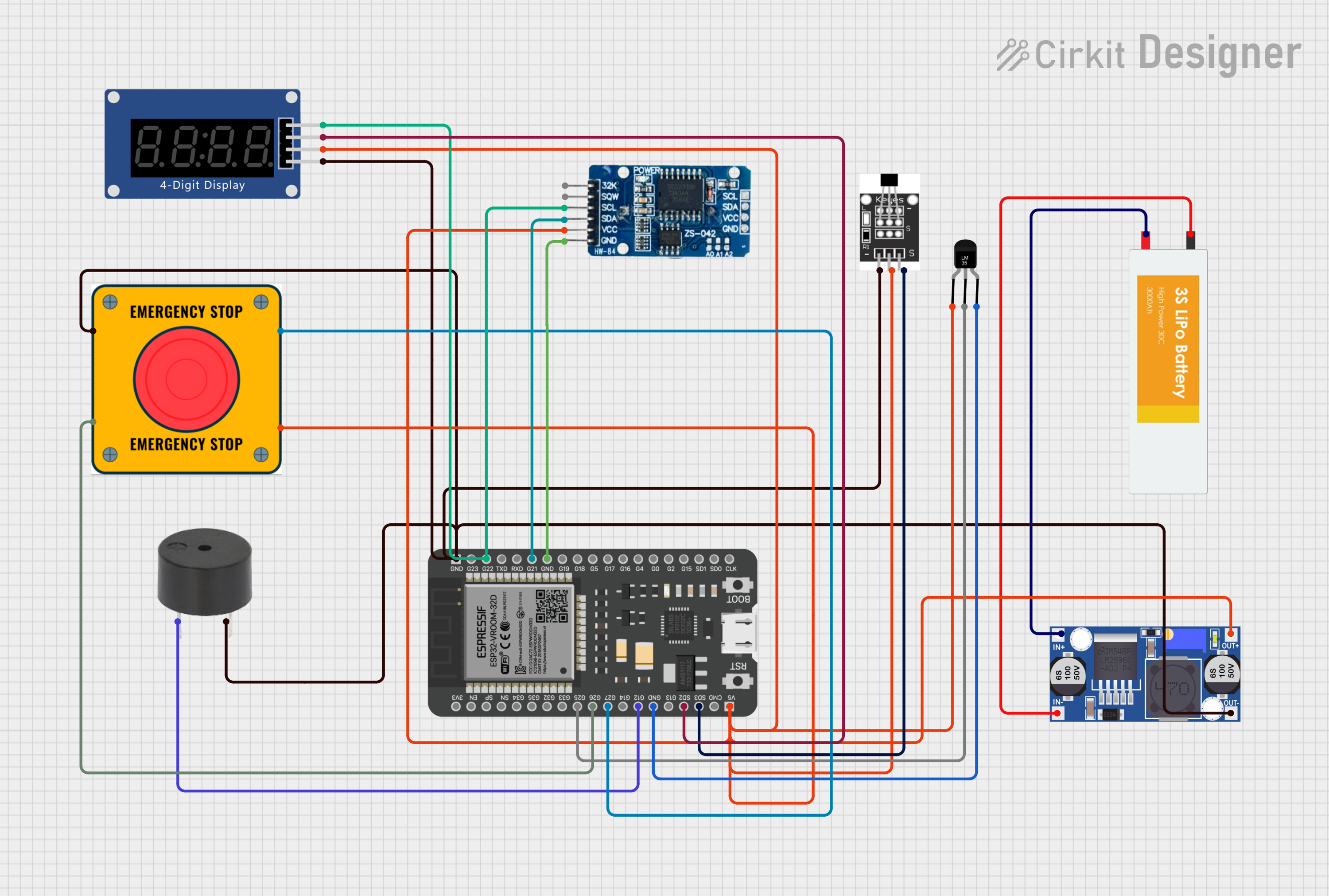
Circuit Documentation
Summary
This circuit is designed to interface various sensors and output devices with an ESP32 microcontroller. It includes a power management system using a Lipo Battery and a Buck Converter to provide stable voltage levels. The circuit features a Hall Sensor and a Temperature Sensor (LM35) for sensing purposes, a Real-Time Clock (RTC DS3231) for timekeeping, a buzzer for audio signaling, an E Stop for emergency power cutoff, and a Seven Segment Display (TM1637) for numeric output.
Component List
Lipo Battery
- Description: A rechargeable battery that provides power to the circuit.
- Pins: VCC, GND
ESP32 - 38 pins
- Description: A microcontroller with Wi-Fi and Bluetooth capabilities, used as the main processing unit of the circuit.
- Pins: 3V3, EN, SP, SN, G34, G35, G32, G33, G25, G26, G27, G14, G12, GND, G13, SD2, SD3, CMD, 5V, G23, G22, TXD, RXD, G21, G19, G18, G5, G17, G16, G4, G0, G2, G15, SD1, SD0, CLK
Hall Sensor
- Description: A sensor that detects magnetic fields.
- Pins: -, +, S
Temperature Sensor (LM35)
- Description: A precision integrated-circuit temperature sensor.
- Pins: +Vs, Vout, GND
Buck Converter
- Description: A DC-DC converter that steps down voltage from the Lipo Battery to a lower level.
- Pins: IN+, IN-, OUT+, OUT-
RTC DS3231
- Description: A highly accurate I2C real-time clock with an integrated temperature-compensated crystal oscillator (TCXO) and crystal.
- Pins: 32K, SQW, SCL, SDA, VCC, GND
Buzzer
- Description: An audio signaling device.
- Pins: PIN, GND
E Stop
- Description: An emergency stop switch that can interrupt power or signal lines.
- Pins: NO 1, NO 2, NC 1, NC 2
Seven Segment Display (TM1637) (Wokwi Compatible)
- Description: A display module for showing numerical data, controlled via a digital interface.
- Pins: CLK, DIO, VCC, GND
Wiring Details
Lipo Battery
- VCC connected to Buck Converter IN+
- GND connected to Buck Converter IN-
ESP32 - 38 pins
- G25 connected to Temperature Sensor (LM35) Vout
- G26 connected to E Stop NC 1
- G27 connected to E Stop NO 2
- G12 connected to Buzzer PIN
- GND connected to Temperature Sensor (LM35) GND, Buzzer GND, Seven Segment Display (TM1637) GND, RTC DS3231 GND, Hall Sensor -
- SD2 connected to Seven Segment Display (TM1637) DIO
- SD3 connected to Hall Sensor S
- 5V connected to E Stop NC 2, Temperature Sensor (LM35) +Vs, Buck Converter OUT+, Seven Segment Display (TM1637) VCC, RTC DS3231 VCC, Hall Sensor +
- G22 connected to Seven Segment Display (TM1637) CLK, RTC DS3231 SCL
- G21 connected to RTC DS3231 SDA
Hall Sensor
-
- connected to ESP32 GND
-
- connected to ESP32 5V
- S connected to ESP32 SD3
Temperature Sensor (LM35)
- +Vs connected to ESP32 5V
- Vout connected to ESP32 G25
- GND connected to ESP32 GND
Buck Converter
- IN+ connected to Lipo Battery VCC
- IN- connected to Lipo Battery GND
- OUT+ connected to ESP32 5V
- OUT- connected to ESP32 GND
RTC DS3231
- SCL connected to ESP32 G22
- SDA connected to ESP32 G21
- VCC connected to ESP32 5V
- GND connected to ESP32 GND
Buzzer
- PIN connected to ESP32 G12
- GND connected to ESP32 GND
E Stop
- NC 1 connected to ESP32 G26
- NO 2 connected to ESP32 G27
- NC 2 connected to ESP32 5V
- NO 1 connected to ESP32 GND
Seven Segment Display (TM1637) (Wokwi Compatible)
- CLK connected to ESP32 G22
- DIO connected to ESP32 SD2
- VCC connected to ESP32 5V
- GND connected to ESP32 GND
Documented Code
No code was provided for the microcontroller. The documentation of the code would typically include a description of the functionality, setup and loop functions, and any additional functions or libraries used to control the components in the circuit.