
Arduino 101 Bluetooth-Controlled Robotic System with Joystick and Ultrasonic Sensors
View and Edit Project In Cirkit Designer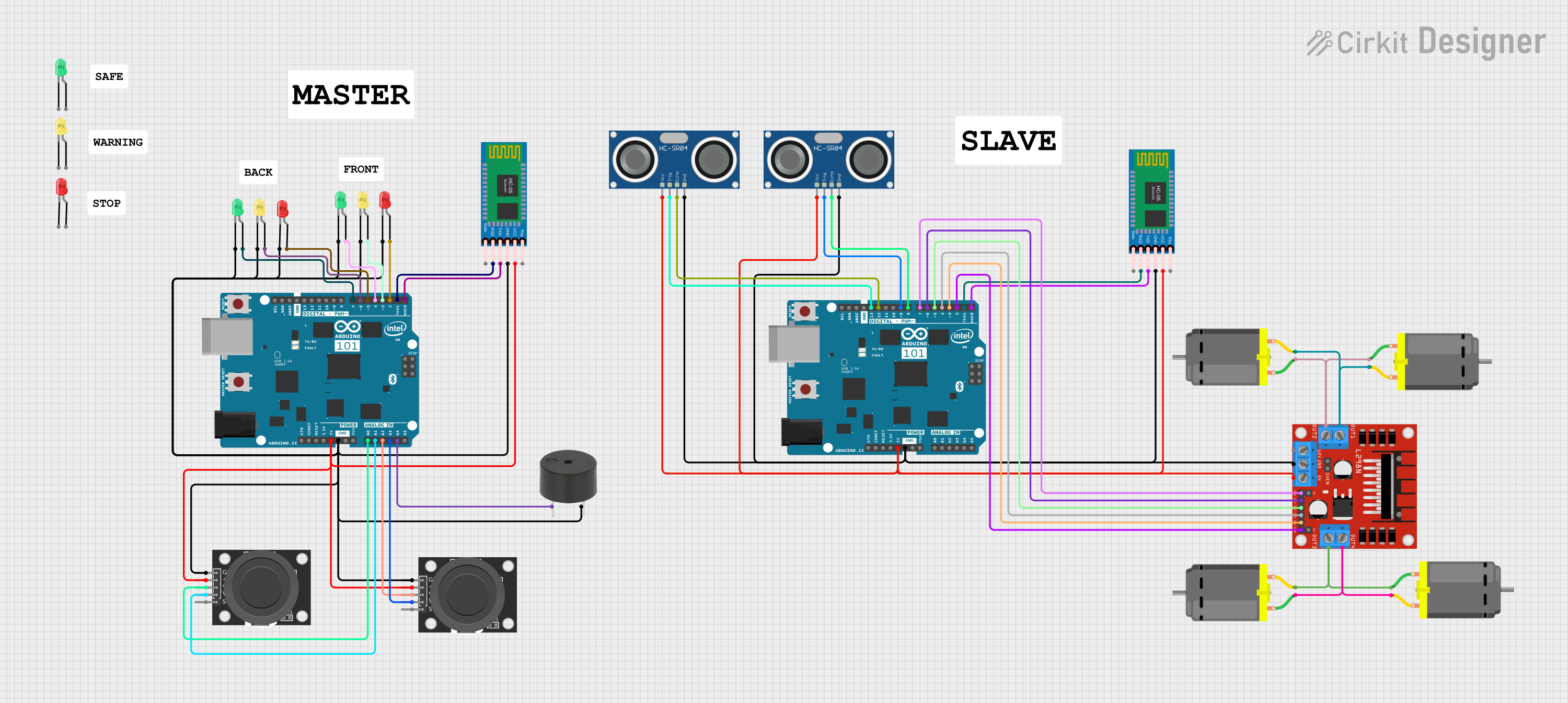
Circuit Documentation
Summary
This circuit involves an Arduino 101 microcontroller interfacing with various components including LEDs, a buzzer, a joystick module, a Bluetooth module, an ultrasonic sensor, and a DC motor driver. The circuit is designed to read joystick inputs, control LEDs and a buzzer, and communicate via Bluetooth. Additionally, it controls DC motors using an L298N motor driver.
Component List
KY-023 Dual Axis Joystick Module
- Pins: GND, +5V, VRx, VRy, SW
- Description: A joystick module used to provide analog input for x and y axes.
Arduino 101
- Pins: A5/SCL, A4/SDA, AREF, GND, D13/SCK, D12/MISO, D11 PWM/MOSI, D10 PWM/SS, D9 PWM, D8, D7, D6 PWM, D5 PWM, D4, D3 PWM, D2, D1/TX, D0/RX, AIN, ioref, RESET, 3V3, 5V, VIN, A0, A1, A2, A3, ICSP MISO, ICSP SCK, ICSP MOSI
- Description: A microcontroller board used to control the circuit and interface with various components.
LED: Two Pin (red)
- Pins: cathode, anode
- Description: A red LED used for visual indication.
LED: Two Pin (yellow)
- Pins: cathode, anode
- Description: A yellow LED used for visual indication.
LED: Two Pin (green)
- Pins: cathode, anode
- Description: A green LED used for visual indication.
L298N DC Motor Driver
- Pins: OUT1, OUT2, 12V, GND, 5V, OUT3, OUT4, 5V-ENA-JMP-I, 5V-ENA-JMP-O, +5V-J1, +5V-J2, ENA, IN1, IN2, IN3, IN4, ENB
- Description: A motor driver used to control DC motors.
DC Motor
- Pins: pin 1, pin 2
- Description: A DC motor used for mechanical movement.
HC-05 Bluetooth Module
- Pins: Key, VCC, GND, TXD, RXD, State
- Description: A Bluetooth module used for wireless communication.
HC-SR04 Ultrasonic Sensor
- Pins: VCC, TRIG, ECHO, GND
- Description: An ultrasonic sensor used for distance measurement.
Buzzer
- Pins: PIN, GND
- Description: A buzzer used for audio indication.
Wiring Details
KY-023 Dual Axis Joystick Module
- GND: Connected to GND of Arduino 101
- +5V: Connected to +5V of Arduino 101
- VRx: Connected to A2 (first joystick) and A0 (second joystick) of Arduino 101
- VRy: Connected to A3 (first joystick) and A1 (second joystick) of Arduino 101
Arduino 101
- D7: Connected to anode of green LED
- D6 PWM: Connected to anode of yellow LED
- D5 PWM: Connected to anode of red LED
- D4: Connected to anode of green LED
- D3 PWM: Connected to anode of yellow LED
- D2: Connected to anode of red LED
- D1/TX: Connected to RXD of HC-05 Bluetooth Module
- D0/RX: Connected to TXD of HC-05 Bluetooth Module
- 5V: Connected to +5V of KY-023 Joystick Modules, VCC of HC-05 Bluetooth Module, VCC of HC-SR04 Ultrasonic Sensors, and 5V of L298N Motor Driver
- GND: Connected to GND of KY-023 Joystick Modules, GND of HC-05 Bluetooth Module, GND of HC-SR04 Ultrasonic Sensors, and GND of L298N Motor Driver
- A0: Connected to VRx of second KY-023 Joystick Module
- A1: Connected to VRy of second KY-023 Joystick Module
- A2: Connected to VRx of first KY-023 Joystick Module
- A3: Connected to VRy of first KY-023 Joystick Module
- A4/SDA: Connected to PIN of Buzzer
- D13/SCK: Connected to TRIG of first HC-SR04 Ultrasonic Sensor
- D12/MISO: Connected to ECHO of first HC-SR04 Ultrasonic Sensor
- D9 PWM: Connected to TRIG of second HC-SR04 Ultrasonic Sensor
- D8: Connected to ECHO of second HC-SR04 Ultrasonic Sensor
LED: Two Pin (red)
- anode: Connected to D5 PWM and D2 of Arduino 101
- cathode: Connected to GND
LED: Two Pin (yellow)
- anode: Connected to D6 PWM and D3 PWM of Arduino 101
- cathode: Connected to GND
LED: Two Pin (green)
- anode: Connected to D7 and D4 of Arduino 101
- cathode: Connected to GND
L298N DC Motor Driver
- ENA: Connected to D7 of Arduino 101
- IN1: Connected to D6 PWM of Arduino 101
- IN2: Connected to D5 PWM of Arduino 101
- IN3: Connected to D4 of Arduino 101
- IN4: Connected to D3 PWM of Arduino 101
- ENB: Connected to D2 of Arduino 101
- OUT1: Connected to pin 2 of two DC Motors
- OUT2: Connected to pin 1 of two DC Motors
- OUT3: Connected to pin 2 of one DC Motor and pin 1 of another DC Motor
- OUT4: Connected to pin 1 of one DC Motor and pin 2 of another DC Motor
- 5V: Connected to 5V of Arduino 101
- GND: Connected to GND of Arduino 101
DC Motor
- pin 1: Connected to OUT2 and OUT4 of L298N Motor Driver
- pin 2: Connected to OUT1 and OUT3 of L298N Motor Driver
HC-05 Bluetooth Module
- RXD: Connected to D1/TX of Arduino 101
- TXD: Connected to D0/RX of Arduino 101
- VCC: Connected to 5V of Arduino 101
- GND: Connected to GND of Arduino 101
HC-SR04 Ultrasonic Sensor
- TRIG: Connected to D13/SCK and D9 PWM of Arduino 101
- ECHO: Connected to D12/MISO and D8 of Arduino 101
- VCC: Connected to 5V of Arduino 101
- GND: Connected to GND of Arduino 101
Buzzer
- PIN: Connected to A4/SDA of Arduino 101
- GND: Connected to GND
Code Documentation
Arduino 101 (Main Controller)
/*
 * Arduino Joystick Controller
 * This code reads values from two KY-023 Dual Axis Joystick Modules and sends
 * the data via Bluetooth using an HC-05 Bluetooth Module. It also controls an
 * LED and a buzzer based on received Bluetooth commands and IR sensor inputs.
 */

#include <SoftwareSerial.h>

#define greenLedPin 8
#define BUZZER_PIN A4
#define ENA_PIN 10
#define IN1_PIN 9
#define IN2_PIN 8
#define IN3_PIN 7
#define IN4_PIN 6
#define ENB_PIN 5

SoftwareSerial btSerial(2, 3); // RX | TX

struct PacketData {
  byte lxAxisValue;
  byte lyAxisValue;
  byte rxAxisValue;
  byte ryAxisValue;
};

PacketData data;
int dataFromSlave = 0;

void setup() {
  pinMode(greenLedPin, OUTPUT);
  digitalWrite(greenLedPin, LOW);
  pinMode(BUZZER_PIN, INPUT);
  digitalWrite(BUZZER_PIN, LOW);
  pinMode(ENA_PIN, OUTPUT);
  pinMode(IN1_PIN, OUTPUT);
  pinMode(IN2_PIN, OUTPUT);
  pinMode(IN3_PIN, OUTPUT);
  pinMode(IN4_PIN, OUTPUT);
  pinMode(ENB_PIN, OUTPUT);
  btSerial.begin(38400);
  Serial.begin(9600);
}

int Joystick(int value, bool reverse)