Arduino Leonardo-Controlled Servo Array with Bluetooth and Neurosky Sensor Integration
Circuit Documentation
Summary
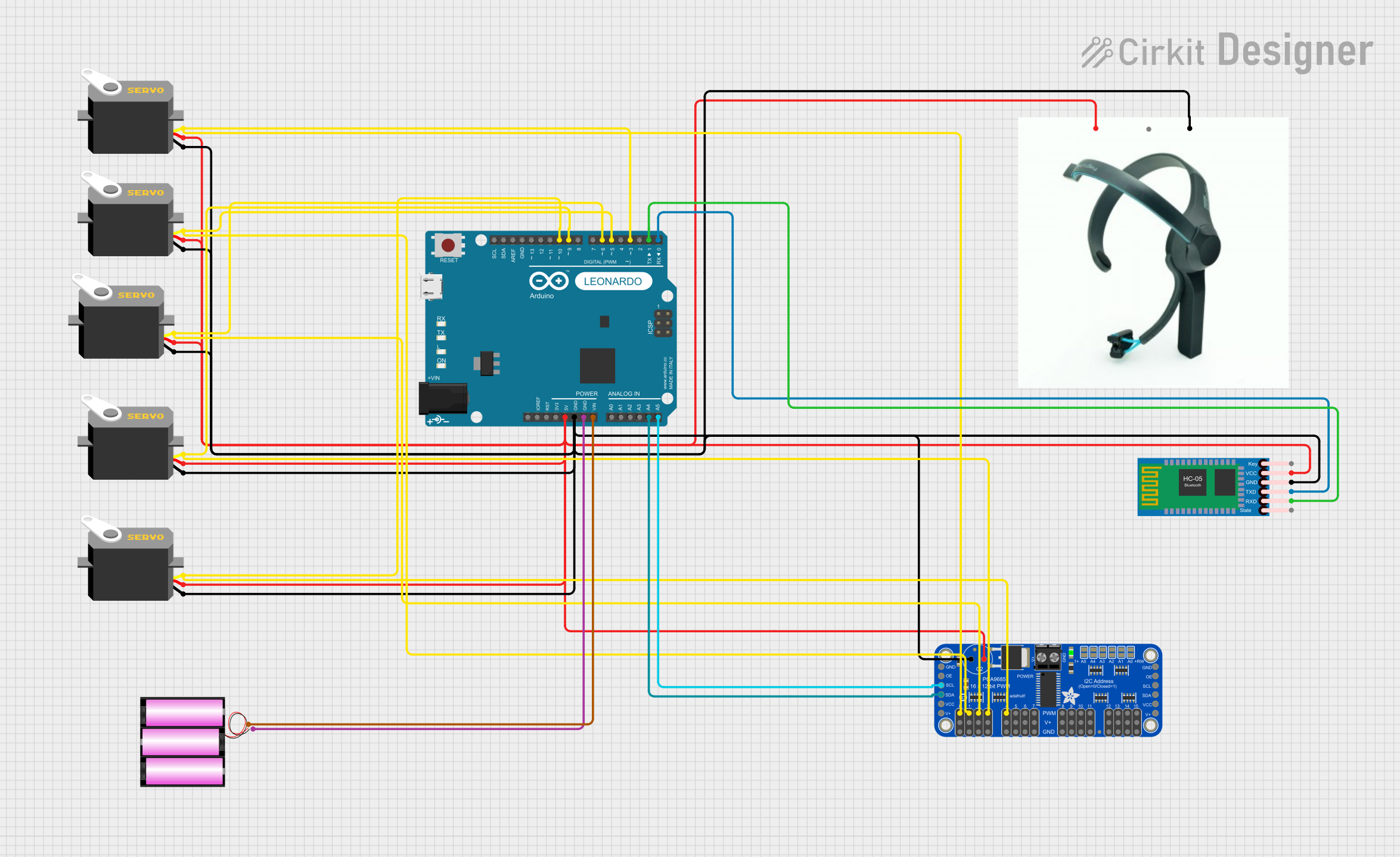
The circuit in question is designed to interface an Arduino Leonardo (Rev3b) with multiple servo motors, an HC-05 Bluetooth module, a Neurosky Sensor, and an Adafruit PCA9685 PWM Servo Breakout board. The circuit is powered by a 12V battery, and it includes communication between the Arduino and the Bluetooth module, as well as the Neurosky Sensor. The servos are controlled via PWM signals, which are generated by the Arduino and the PCA9685 breakout board. The circuit is intended for wireless control of servos, possibly for a robotic or remote control application, with inputs from a Neurosky Sensor.
Component List
Arduino Leonardo (Rev3b)
- Microcontroller board based on the ATmega32u4
- Features digital I/O pins, analog inputs, a USB connection, and other peripherals
Servo Motors
- Actuators that can be precisely controlled in terms of angular or linear position, velocity, and acceleration
- Each servo has three connections: ground (gnd), power (vcc), and control signal (pulse)
HC-05 Bluetooth Module
- Wireless communication module that allows for serial communication over Bluetooth
- Has pins for key, power (VCC), ground (GND), transmit (TXD), receive (RXD), and state
Neurosky Sensor
- Brainwave sensor module with pins for power (VCC), data output (DATA), and ground (GND)
Adafruit PCA9685 PWM Servo Breakout
- 16-channel, 12-bit PWM Fm+ I2C-bus LED controller
- Used for driving multiple PWM outputs, such as servo motors
Battery 12V
- Power source for the circuit
Wiring Details
Arduino Leonardo (Rev3b)
D0/RXconnected to HC-05 Bluetooth ModuleTXDD1/TXconnected to HC-05 Bluetooth ModuleRXDD3 PWM/SCL,D5 PWM,D6 PWM/A7,D9 PWM/A9,D10 PWM/A10connected to corresponding servo motors and Adafruit PCA9685 PWM Servo Breakout PWM outputs5Vconnected to the VCC of all servos, HC-05 Bluetooth Module, Neurosky Sensor, and Adafruit PCA9685 PWM Servo BreakoutGNDconnected to the ground of all components and the negative terminal of the batteryVINconnected to the positive terminal of the batteryA4connected to Adafruit PCA9685 PWM Servo BreakoutSDAA5connected to Adafruit PCA9685 PWM Servo BreakoutSCL
Servo Motors
gndconnected to common groundvccconnected to 5V from Arduino Leonardo (Rev3b)pulseconnected to corresponding PWM outputs on Arduino Leonardo (Rev3b) and Adafruit PCA9685 PWM Servo Breakout
HC-05 Bluetooth Module
TXDconnected to Arduino Leonardo (Rev3b)D0/RXRXDconnected to Arduino Leonardo (Rev3b)D1/TXVCCconnected to 5V from Arduino Leonardo (Rev3b)GNDconnected to common ground
Neurosky Sensor
VCCconnected to 5V from Arduino Leonardo (Rev3b)GNDconnected to common ground
Adafruit PCA9685 PWM Servo Breakout
5.0Vconnected to 5V from Arduino Leonardo (Rev3b)GNDconnected to common groundSDAconnected to Arduino Leonardo (Rev3b)A4SCLconnected to Arduino Leonardo (Rev3b)A5PWM0toPWM4connected to corresponding servo motors
Battery 12V
+connected to Arduino Leonardo (Rev3b)VIN-connected to common ground
Documented Code
No code was provided for the microcontrollers in the circuit. Typically, the code would be responsible for initializing the communication interfaces (such as serial for Bluetooth communication), configuring the PWM outputs for servo control, and implementing the logic for responding to sensor inputs or Bluetooth commands to control the servos.