
Arduino UNO Controlled RGB LED Lights with Bluetooth Connectivity
View and Edit Project In Cirkit Designer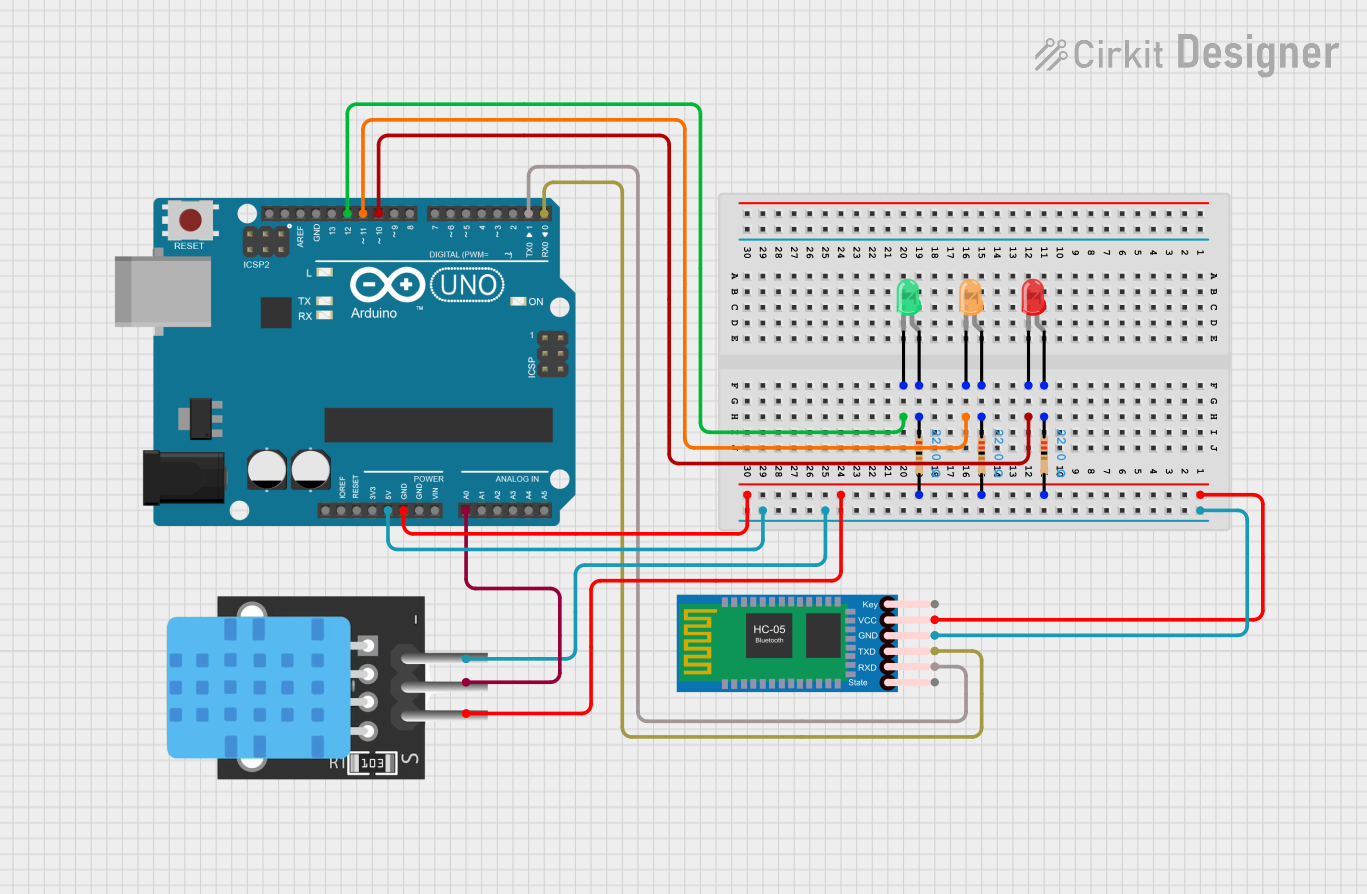
Circuit Documentation
Summary of the Circuit
This circuit is designed around an Arduino UNO microcontroller, which serves as the central processing unit. The circuit includes three LEDs (red, green, and orange), each with a corresponding resistor to limit the current. An HC-05 Bluetooth module is incorporated for wireless communication capabilities. Additionally, a temperature sensor (labeled TEMP) is connected to the Arduino for temperature monitoring. The Arduino UNO is programmed to control the LEDs, communicate with the HC-05 Bluetooth module, and read data from the temperature sensor.
Component List
Arduino UNO
- Description: A microcontroller board based on the ATmega328P.
- Pins: UNUSED, IOREF, Reset, 3.3V, 5V, GND, Vin, A0-A5, SCL, SDA, AREF, D0-D13
LED: Two Pin (red)
- Description: A red light-emitting diode.
- Pins: cathode, anode
LED: Two Pin (green)
- Description: A green light-emitting diode.
- Pins: cathode, anode
LED: Two Pin (orange)
- Description: An orange light-emitting diode.
- Pins: cathode, anode
Resistor (22 Ohms)
- Description: A resistor with a resistance of 22 Ohms.
- Pins: pin1, pin2
HC-05 Bluetooth Module
- Description: A Bluetooth module for wireless communication.
- Pins: Key, VCC, GND, TXD, RXD, State
TEMP (Temperature Sensor)
- Description: A temperature sensor for measuring ambient temperature.
- Pins: 5V, D3, GND
Wiring Details
Arduino UNO
- D10 connected to the cathode of the red LED.
- D11 connected to the cathode of the orange LED.
- D12 connected to the cathode of the green LED.
- GND connected to the GND of the HC-05 Bluetooth Module, TEMP sensor, and the common ground net.
- 5V connected to the VCC of the HC-05 Bluetooth Module and the 5V of the TEMP sensor.
- A0 connected to the D3 of the TEMP sensor.
- D1 (TX) connected to the RXD of the HC-05 Bluetooth Module.
- D0 (RX) connected to the TXD of the HC-05 Bluetooth Module.
LED: Two Pin (red)
- Anode connected to one pin of a 22 Ohm resistor.
LED: Two Pin (green)
- Anode connected to one pin of a 22 Ohm resistor.
LED: Two Pin (orange)
- Anode connected to one pin of a 22 Ohm resistor.
Resistor (22 Ohms)
- Other pin connected to the 5V net, which includes VCC of the HC-05 Bluetooth Module, 5V of the TEMP sensor, and 5V of the Arduino UNO.
HC-05 Bluetooth Module
- Key, State, and unused pins are not connected.
TEMP (Temperature Sensor)
- No additional connections beyond those listed above.
Documented Code
Arduino UNO Code (sketch.ino)
void setup() {
  // put your setup code here, to run once:

}

void loop() {
  // put your main code here, to run repeatedly:

}
Additional Notes
- The code provided is a template and does not contain any functional code to control the circuit components. The user is expected to write the necessary code to initialize the pins, control the LEDs, communicate with the HC-05 Bluetooth module, and read data from the temperature sensor.
- The
setup()function is intended for initialization code that runs once, while theloop()function contains code that runs repeatedly, forming the main logic of the program. - The documentation file (documentation.txt) is empty and can be used to add further explanations or instructions related to the code and circuit operation.