Cirkit Designer
Your all-in-one circuit design IDE
Home /
Project Documentation
Wi-Fi Controlled DC Motor System using ESP8266 and L298N Driver
Circuit Documentation
Summary
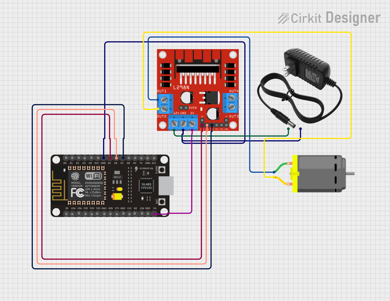
This circuit is designed to control a DC motor using an ESP8266 NodeMCU microcontroller and an L298N motor driver. The ESP8266 NodeMCU sends control signals to the L298N motor driver, which in turn drives the DC motor. A 12V power supply is used to power the motor driver and the motor.
Component List
ESP8266 NodeMCU
- Description: A low-cost Wi-Fi microcontroller with GPIO, PWM, ADC, and more.
- Pins: D0, D1, D2, D3, D4, 3V3, GND, D5, D6, D7, D8, RX, TX, A0, RSV, SD3, SD2, SD1, CMD, SD0, CLK, EN, RST, VIN
DC Motor
- Description: A simple DC motor with two terminals for power.
- Pins: pin 1, pin 2
12V Power Supply
- Description: A power supply providing 12V DC.
- Pins: +, -
L298N DC Motor Driver
- Description: A dual H-Bridge motor driver that can control the speed and direction of two DC motors.
- Pins: OUT1, OUT2, 12V, GND, 5V, OUT3, OUT4, 5V-ENA-JMP-I, 5V-ENA-JMP-O, +5V-J1, +5V-J2, ENA, IN1, IN2, IN3, IN4, ENB
Wiring Details
ESP8266 NodeMCU
- GND connected to GND of the 12V power supply and L298N motor driver.
- D5 connected to ENA of the L298N motor driver.
- D6 connected to IN1 of the L298N motor driver.
- D7 connected to IN2 of the L298N motor driver.
- VIN connected to 5V of the L298N motor driver.
DC Motor
- pin 1 connected to OUT1 of the L298N motor driver.
- pin 2 connected to OUT2 of the L298N motor driver.
12V Power Supply
- - connected to GND of the ESP8266 NodeMCU and L298N motor driver.
- + connected to 12V of the L298N motor driver.
L298N DC Motor Driver
- GND connected to GND of the 12V power supply and ESP8266 NodeMCU.
- ENA connected to D5 of the ESP8266 NodeMCU.
- IN1 connected to D6 of the ESP8266 NodeMCU.
- IN2 connected to D7 of the ESP8266 NodeMCU.
- 5V connected to VIN of the ESP8266 NodeMCU.
- OUT1 connected to pin 1 of the DC motor.
- OUT2 connected to pin 2 of the DC motor.
- 12V connected to + of the 12V power supply.
Code Documentation
ESP8266 NodeMCU Code
#include <L298N.h>

const unsigned int IN1 = 6;
const unsigned int IN2 = 7;
const unsigned int EN = 5;

L298N motor(EN, IN1, IN2);

void setup()
{
  Serial.begin(9600);
  while (!Serial)
  { }
  motor.setSpeed(70);
}

void loop()
{
  motor.forward();
  printSomeInfo();
  delay(3000);
  motor.stop();
  printSomeInfo();
  motor.setSpeed(255);
  delay(3000);
  motor.backward();
  printSomeInfo();
  motor.setSpeed(120);
  delay(3000);
  motor.stop();
  printSomeInfo();
  delay(3000);
}

void printSomeInfo()
{
  Serial.print("Motor is moving = ");
  Serial.print(motor.isMoving());
  Serial.print(" at speed = ");
  Serial.println(motor.getSpeed());
}
Code Explanation
- Libraries: The code includes the
L298Nlibrary to control the motor driver. - Pin Definitions: The pins for
IN1,IN2, andENare defined. - Motor Initialization: An instance of the
L298Nclass is created with the defined pins. - Setup Function: Initializes the serial communication and sets the initial motor speed to 70.
- Loop Function: Controls the motor to move forward, stop, move backward, and stop again with varying speeds and delays.
- printSomeInfo Function: Prints the motor's movement status and speed to the serial monitor.
This documentation provides a comprehensive overview of the circuit, including the components used, their wiring, and the code running on the ESP8266 NodeMCU.