Arduino Uno R3 Sound-Activated Relay Switch

Circuit Documentation
Summary of the Circuit
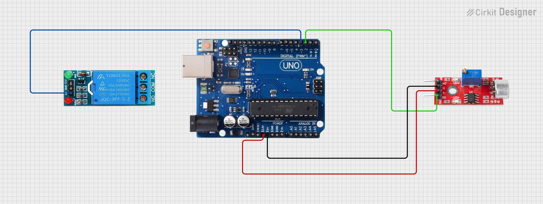
This circuit is designed to interface a sound sensor with an Arduino Uno R3 and control a 12V single-channel relay based on the sound level detected by the sensor. The sound sensor's digital output is connected to one of the digital I/O pins of the Arduino, which processes the signal and controls the relay accordingly. The relay can be used to switch higher power loads on and off. The circuit is powered by the Arduino's 5V output, which is suitable for both the sound sensor and the relay's control circuitry.
Component List
Sound Sensor
- Pins: Analog, GND, VCC, Digital
- Description: A sensor that detects sound levels and provides both analog and digital outputs.
- Purpose: To detect sound levels and provide a digital signal to the Arduino when a certain threshold is reached.
Arduino Uno R3
- Pins: USB Port, Power Jack, Not Connected, IOREF, RESET, 3.3V, 5V, GND, VIN, A0-A5, SCL, SDA, AREF, D0-D13
- Description: A microcontroller board based on the ATmega328P, widely used for building digital devices and interactive objects that can sense and control objects in the physical world.
- Purpose: To process the digital signal from the sound sensor and control the relay.
12V Single Channel Relay
- Pins: NC, COM, NO, IN, GND, VCC
- Description: An electrically operated switch that allows you to control a high power circuit with a low power signal.
- Purpose: To switch on or off a higher power device in response to the Arduino's output.
Wiring Details
Sound Sensor
- GND: Connected to Arduino Uno R3 GND
- VCC: Connected to Arduino Uno R3 5V
- Digital: Connected to Arduino Uno R3 Digital Pin 2
Arduino Uno R3
- 5V: Provides power to Sound Sensor VCC and Relay VCC
- GND: Common ground for Sound Sensor and Relay
- Digital Pin 2: Receives digital signal from Sound Sensor
- Digital Pin 3: Outputs control signal to Relay IN
12V Single Channel Relay
- IN: Connected to Arduino Uno R3 Digital Pin 3
- GND: Connected to Arduino Uno R3 GND
- VCC: Connected to Arduino Uno R3 5V
Documented Code
Since no code was provided, this section is left blank. The expected code would typically include setup and loop functions, where the setup function initializes the digital pins and the loop function reads the sound sensor's digital output and controls the relay accordingly.