Cirkit Designer
Your all-in-one circuit design IDE
Home /
Project Documentation
Arduino Mega 2560 Battery-Powered Dual DC Motor Control System
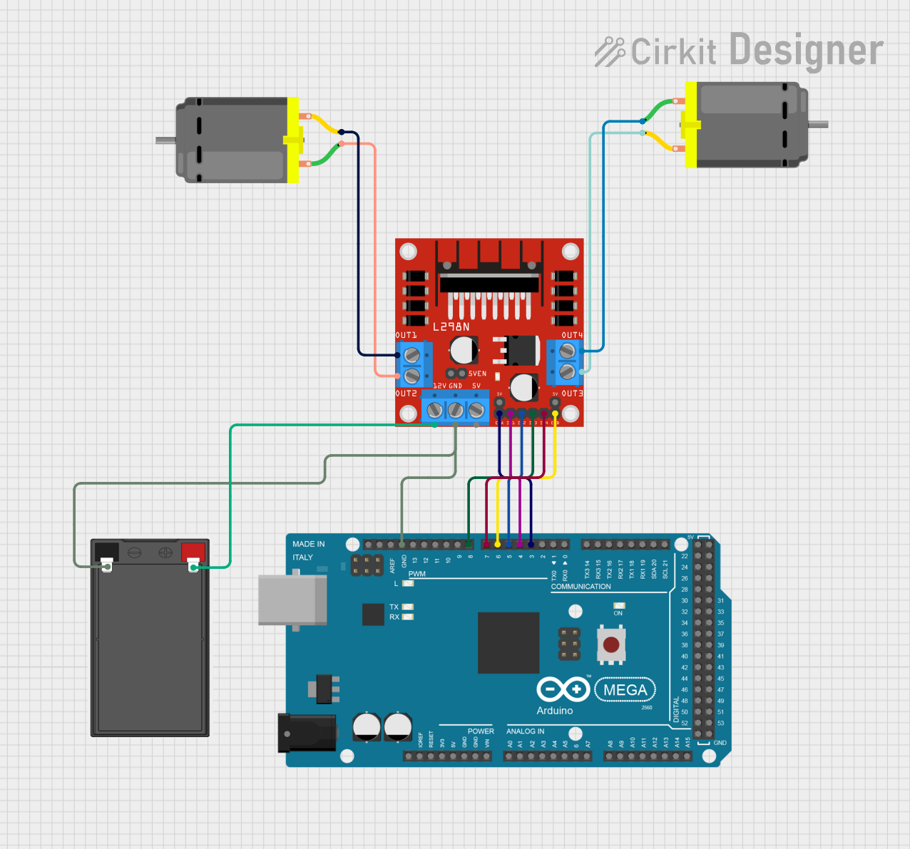
Circuit Documentation
Summary
This circuit consists of an Arduino Mega 2560 microcontroller, an L298N DC motor driver, two DC motors, and a battery. The Arduino Mega 2560 controls the L298N motor driver, which in turn drives the two DC motors. The battery provides power to the motor driver and the Arduino.
Component List
Arduino Mega 2560
- Description: A microcontroller board based on the ATmega2560.
- Pins: IOREF, RESET, 3V3, 5V, GND, VIN, A0-A15, D0-D53, AREF, SDA, SCL
L298N DC Motor Driver
- Description: A dual H-Bridge motor driver that allows control of two DC motors.
- Pins: OUT1, OUT2, 12V, GND, 5V, OUT3, OUT4, 5V-ENA-JMP-I, 5V-ENA-JMP-O, +5V-J1, +5V-J2, ENA, IN1, IN2, IN3, IN4, ENB
DC Motor (Motor 1)
- Description: A standard DC motor.
- Pins: pin 1, pin 2
DC Motor (Motor 2)
- Description: A standard DC motor.
- Pins: pin 1, pin 2
Battery
- Description: A power source for the circuit.
- Pins: -, +
Wiring Details
Arduino Mega 2560
- D3 PWM connected to ENA of L298N DC motor driver
- D4 PWM connected to IN1 of L298N DC motor driver
- D5 PWM connected to IN2 of L298N DC motor driver
- D6 PWM connected to ENB of L298N DC motor driver
- D7 PWM connected to IN4 of L298N DC motor driver
- D8 PWM connected to IN3 of L298N DC motor driver
- GND connected to GND of L298N DC motor driver and - of battery
L298N DC Motor Driver
- ENA connected to D3 PWM of Arduino Mega 2560
- IN1 connected to D4 PWM of Arduino Mega 2560
- IN2 connected to D5 PWM of Arduino Mega 2560
- ENB connected to D6 PWM of Arduino Mega 2560
- IN4 connected to D7 PWM of Arduino Mega 2560
- IN3 connected to D8 PWM of Arduino Mega 2560
- GND connected to GND of Arduino Mega 2560 and - of battery
- OUT1 connected to pin 2 of DC Motor 2
- OUT2 connected to pin 1 of DC Motor 2
- OUT3 connected to pin 2 of DC Motor 1
- OUT4 connected to pin 1 of DC Motor 1
- 12V connected to + of battery
DC Motor (Motor 1)
- pin 1 connected to OUT4 of L298N DC motor driver
- pin 2 connected to OUT3 of L298N DC motor driver
DC Motor (Motor 2)
- pin 1 connected to OUT2 of L298N DC motor driver
- pin 2 connected to OUT1 of L298N DC motor driver
Battery
- - connected to GND of L298N DC motor driver and GND of Arduino Mega 2560
- + connected to 12V of L298N DC motor driver
Documented Code
Arduino Mega 2560 Code (sketch.ino)
void setup() {
  // put your setup code here, to run once:

}

void loop() {
  // put your main code here, to run repeatedly:

}
Additional Documentation (documentation.txt)