
Arduino Mega 2560-Based Automatic Filling Device with Humidity, Temperature, and Water Level Monitoring
View and Edit Project In Cirkit Designer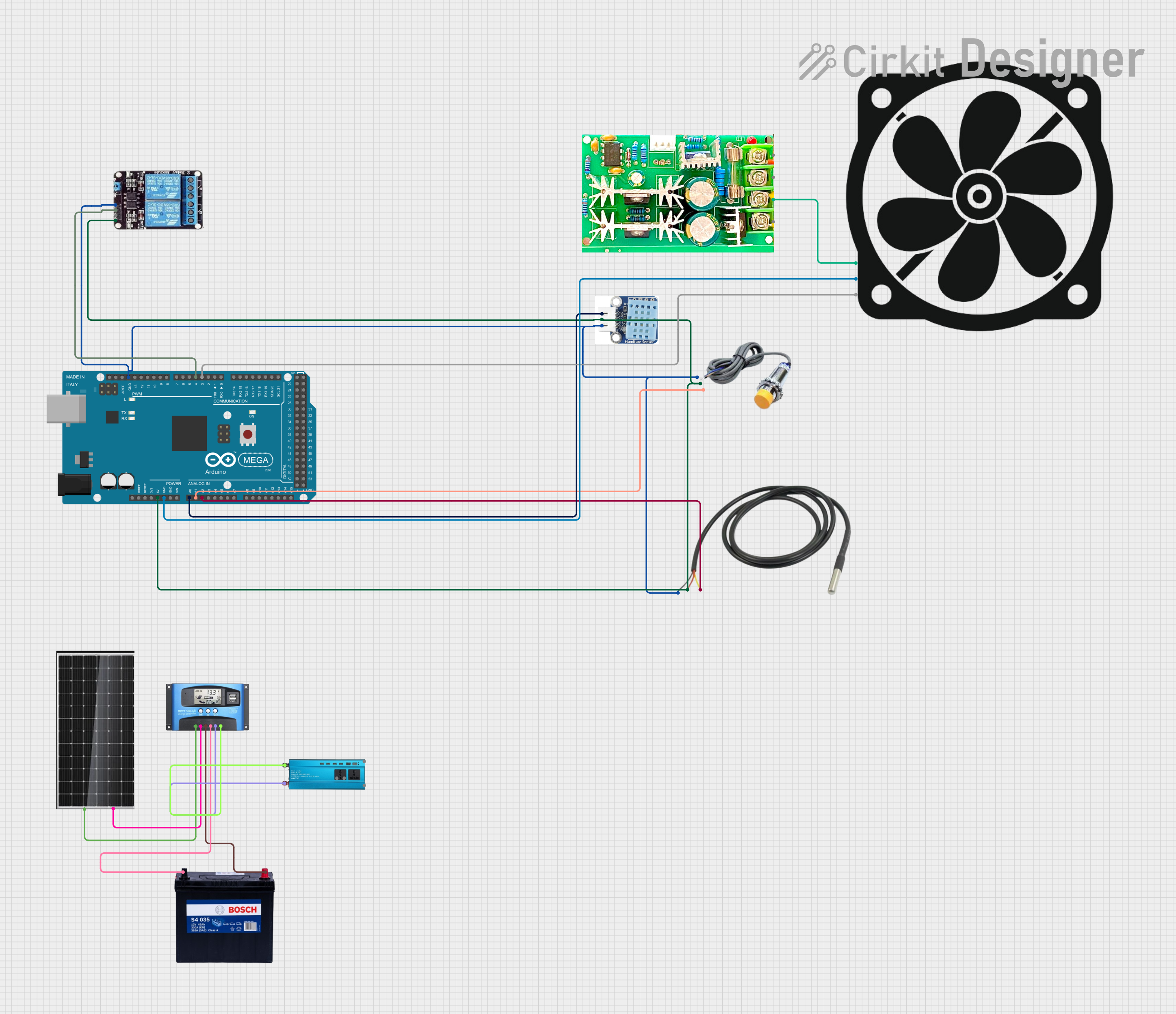
Circuit Documentation
Summary
This circuit is an automatic filling device that controls a fan, compressor, and monitors humidity, water level, and temperature. The fan speed is adjusted based on humidity levels, the compressor is controlled via a relay module, and the water level is monitored using a capacitive sensor. The system is powered by a solar panel and battery setup, with an MPPT charge controller and a solar inverter for DC to AC conversion.
Component List
Arduino Mega 2560
- Description: Microcontroller board based on the ATmega2560.
- Pins: IOREF, RESET, 3V3, 5V, GND, VIN, A0-A15, D0-D53, AREF, SDA, SCL.
Capacitive Sensor
- Description: Sensor to measure water level.
- Pins: GND, VCC, SIGNAL.
Temperature Sensor
- Description: Sensor to measure temperature.
- Pins: Temp GND Black, Temp VDD Red, Temp DQ Data Yellow.
Humiture Sensor
- Description: Sensor to measure humidity.
- Pins: SIG, VCC, GND.
PC Fan
- Description: Fan for cooling purposes.
- Pins: 12V, GND, PWM.
PWM Motor Speed Controller
- Description: Controller to adjust motor speed using PWM.
- Pins: Motor+, Motor-, Power-, Power+, PWM.
2ch Relay
- Description: Relay module to control high-power devices.
- Pins: NC, COM, NO, VCC, IN2, IN1, GND.
Solar Panel 380W
- Description: Solar panel to generate electricity.
- Pins: -, +.
MPPT SCC
- Description: Maximum Power Point Tracking Solar Charge Controller.
- Pins: SOLAR+, SOLAR-, BATTERY+, BATTERY-, LOAD+, LOAD-.
12V 200Ah Battery
- Description: Battery to store energy.
- Pins: GND, 12V.
Solar Inverter DC TO AC
- Description: Inverter to convert DC to AC.
- Pins: SOLAR +, Solar -, OUT -, OUT +, Battery +, Battery -.
Wiring Details
Arduino Mega 2560
- 5V: Connected to VCC of Capacitive Sensor, Humiture Sensor, Temperature Sensor, and 2ch Relay.
- GND: Connected to GND of Capacitive Sensor, Humiture Sensor, Temperature Sensor, 2ch Relay, and PC Fan.
- A0: Connected to SIG of Humiture Sensor.
- A1: Connected to SIGNAL of Capacitive Sensor.
- A2: Connected to Temp DQ Data Yellow of Temperature Sensor.
- D3 PWM: Connected to PWM of PC Fan.
- D4 PWM: Connected to IN1 of 2ch Relay.
Capacitive Sensor
- VCC: Connected to 5V of Arduino Mega 2560.
- GND: Connected to GND of Arduino Mega 2560.
- SIGNAL: Connected to A1 of Arduino Mega 2560.
Temperature Sensor
- Temp VDD Red: Connected to 5V of Arduino Mega 2560.
- Temp GND Black: Connected to GND of Arduino Mega 2560.
- Temp DQ Data Yellow: Connected to A2 of Arduino Mega 2560.
Humiture Sensor
- VCC: Connected to 5V of Arduino Mega 2560.
- GND: Connected to GND of Arduino Mega 2560.
- SIG: Connected to A0 of Arduino Mega 2560.
PC Fan
- 12V: Connected to Motor+ of PWM Motor Speed Controller.
- GND: Connected to GND of Arduino Mega 2560.
- PWM: Connected to D3 PWM of Arduino Mega 2560.
PWM Motor Speed Controller
- Motor+: Connected to 12V of PC Fan.
2ch Relay
- VCC: Connected to 5V of Arduino Mega 2560.
- GND: Connected to GND of Arduino Mega 2560.
- IN1: Connected to D4 PWM of Arduino Mega 2560.
Solar Panel 380W
- -: Connected to SOLAR- of MPPT SCC.
- +: Connected to SOLAR+ of MPPT SCC.
MPPT SCC
- SOLAR-: Connected to - of Solar Panel 380W.
- SOLAR+: Connected to + of Solar Panel 380W.
- BATTERY+: Connected to 12V of 12V 200Ah Battery.
- BATTERY-: Connected to GND of 12V 200Ah Battery.
- LOAD+: Connected to SOLAR + of Solar Inverter DC TO AC.
- LOAD-: Connected to Solar - of Solar Inverter DC TO AC.
12V 200Ah Battery
- GND: Connected to BATTERY- of MPPT SCC.
- 12V: Connected to BATTERY+ of MPPT SCC.
Solar Inverter DC TO AC
- SOLAR +: Connected to LOAD+ of MPPT SCC.
- Solar -: Connected to LOAD- of MPPT SCC.
Code Documentation
/*
 * Automatic Filling Device
 * This code controls a fan, compressor, and monitors humidity, water level,
 * and temperature. The fan speed is adjusted based on humidity levels. The
 * compressor is controlled via a relay module, and the water level is monitored
 * using a capacitive sensor.
 */

#include <DHT.h>

#define HUMIDITY_SENSOR_PIN A0
#define CAPACITIVE_SENSOR_PIN A1
#define TEMP_SENSOR_PIN A2
#define FAN_PWM_PIN 3
#define RELAY_PIN 4

DHT dht(HUMIDITY_SENSOR_PIN, DHT11);

void setup() {
  Serial.begin(9600);
  dht.begin();
  pinMode(CAPACITIVE_SENSOR_PIN, INPUT);
  pinMode(TEMP_SENSOR_PIN, INPUT);
  pinMode(FAN_PWM_PIN, OUTPUT);
  pinMode(RELAY_PIN, OUTPUT);
}

void loop() {
  float humidity = dht.readHumidity();
  int waterLevel = analogRead(CAPACITIVE_SENSOR_PIN);
  int temperature = analogRead(TEMP_SENSOR_PIN);

  Serial.print("Humidity: ");
  Serial.print(humidity);
  Serial.print("%\tWater Level: ");
  Serial.print(waterLevel);
  Serial.print("%\tTemperature: ");
  Serial.print(temperature);
  Serial.println("C");

  // Control fan speed based on humidity
  int fanSpeed = map(humidity, 0, 100, 255, 0);
  analogWrite(FAN_PWM_PIN, fanSpeed);

  // Control compressor based on water level
  if (waterLevel > 500) { // Threshold for water level
    digitalWrite(RELAY_PIN, HIGH); // Turn on compressor
  } else {
    digitalWrite(RELAY_PIN, LOW); // Turn off compressor
  }

  delay(2000); // Wait for 2 seconds before next reading
}
This code initializes the sensors and actuators, reads the sensor values, and controls the fan speed and compressor based on the humidity and water level readings. The data is also printed to the serial monitor for debugging and monitoring purposes.