
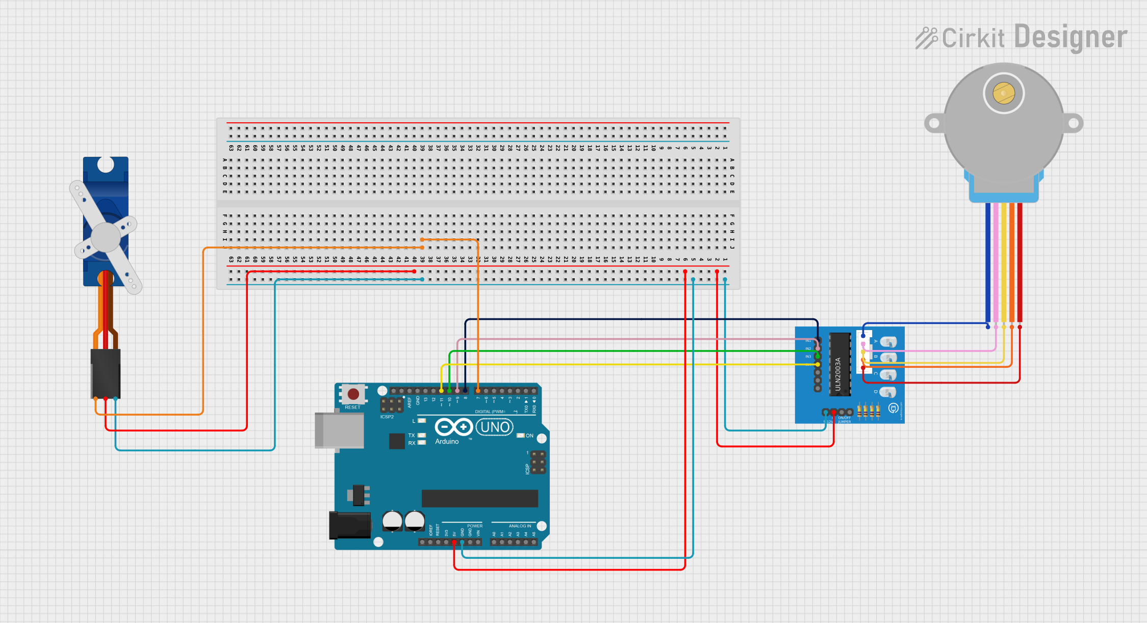
Circuit Documentation
Summary
This circuit integrates a microcontroller (Arduino UNO), a servo motor (Tower Pro SG90), and a stepper motor (28BYJ-48) with its driver board (ULN2003A breakout board). The Arduino UNO controls the servo motor and the stepper motor through digital pins. The servo motor is directly connected to the Arduino for control signals, while the stepper motor is interfaced through the ULN2003A driver board. Power distribution is managed from the Arduino, providing a common ground and +5V to both the servo and the stepper motor driver.
Component List
Arduino UNO
- Microcontroller board based on the ATmega328P
- Pins: UNUSED, IOREF, Reset, 3.3V, 5V, GND, Vin, A0-A5, SCL, SDA, AREF, D0-D13
Tower Pro SG90 Servo
- Small and lightweight servo motor for RC vehicles, helicopters, and drones
- Pins: Signal, +5V, GND
28BYJ-48 Stepper Motor
- Small stepper motor suitable for a wide range of applications
- Pins: BLUE, PINK, YELLOW, ORANGE, RED
ULN2003A Breakout Board
- Breakout board for the ULN2003A stepper motor driver IC
- Pins: In 1-7, 0V, +5V, ON/OFF jumper switch, BLUE wire, PINK wire, YELLOW wire, ORANGE wire, RED wire
Wiring Details
Arduino UNO
- GND connected to common ground net
- 5V connected to common +5V net
- D7 connected to Tower Pro SG90 servo (Signal)
- D8-D11 connected to ULN2003A breakout board (In 1-In 4)
Tower Pro SG90 Servo
- Signal connected to Arduino UNO (D7)
- +5V connected to common +5V net
- GND connected to common ground net
28BYJ-48 Stepper Motor
- BLUE connected to ULN2003A breakout board (BLUE wire)
- PINK connected to ULN2003A breakout board (PINK wire)
- YELLOW connected to ULN2003A breakout board (YELLOW wire)
- ORANGE connected to ULN2003A breakout board (ORANGE wire)
- RED connected to ULN2003A breakout board (RED wire)
ULN2003A Breakout Board
- In 1 connected to Arduino UNO (D8)
- In 2 connected to Arduino UNO (D9)
- In 3 connected to Arduino UNO (D10)
- In 4 connected to Arduino UNO (D11)
- 0V connected to common ground net
- +5V connected to common +5V net
- BLUE wire connected to 28BYJ-48 stepper motor (BLUE)
- PINK wire connected to 28BYJ-48 stepper motor (PINK)
- YELLOW wire connected to 28BYJ-48 stepper motor (YELLOW)
- ORANGE wire connected to 28BYJ-48 stepper motor (ORANGE)
- RED wire connected to 28BYJ-48 stepper motor (RED)
Documented Code
Arduino UNO Code (sketch.ino)
void setup() {
  // put your setup code here, to run once:

}

void loop() {
  // put your main code here, to run repeatedly:

}
Note: The provided code is a template and does not contain any functional code to control the servo or stepper motor. Additional code is required to initialize the pins and implement the control logic for the motors.