
Circuit Documentation
Summary
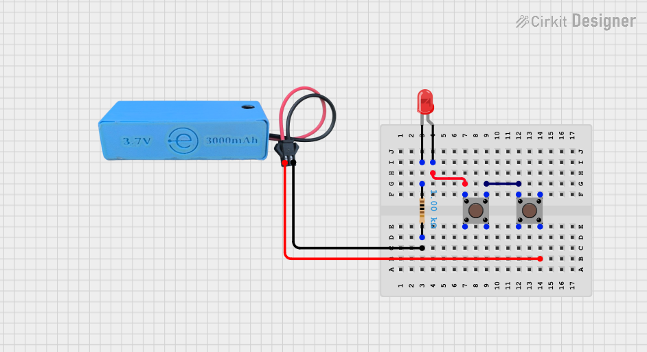
This document provides a detailed description of a simple electronic circuit consisting of a power source, an LED, two pushbuttons, and a resistor. The circuit is designed to control the LED using the pushbuttons. The power source is a MAHIR 1.mini module providing 3.7V and GND connections.
Component List
MAHIR 1.mini
- Pins: GND, 3.7v
- Description: Power source providing 3.7V and GND connections.
- Purpose in Circuit: Supplies power to the circuit.
LED: Two Pin (red)
- Pins: cathode, anode
- Description: A red LED.
- Purpose in Circuit: Indicates the state of the circuit.
Pushbutton (1)
- Pins: Pin 1 (in), Pin 2 (in), Pin 3 (out), Pin 4 (out)
- Description: A pushbutton switch.
- Purpose in Circuit: Used to control the LED.
Pushbutton (2)
- Pins: Pin 1 (in), Pin 2 (in), Pin 3 (out), Pin 4 (out)
- Description: A pushbutton switch.
- Purpose in Circuit: Used to control the LED.
Resistor
- Pins: pin1, pin2
- Description: A resistor with a resistance of 1000 Ohms.
- Purpose in Circuit: Limits the current flowing through the LED.
Wiring Details
MAHIR 1.mini
- GND is connected to pin2 of the Resistor.
- 3.7v is connected to Pin 4 (out) of the second Pushbutton.
LED: Two Pin (red)
- anode is connected to Pin 1 (in) of the first Pushbutton.
- cathode is connected to pin1 of the Resistor.
Pushbutton (1)
- Pin 1 (in) is connected to anode of the LED.
- Pin 3 (out) is connected to Pin 1 (in) of the second Pushbutton.
Pushbutton (2)
- Pin 1 (in) is connected to Pin 3 (out) of the first Pushbutton.
- Pin 4 (out) is connected to 3.7v of the MAHIR 1.mini.
Resistor
- pin1 is connected to cathode of the LED.
- pin2 is connected to GND of the MAHIR 1.mini.
Code
There is no microcontroller code provided for this circuit.
This document provides a comprehensive overview of the circuit, including a summary, detailed component list, wiring details, and code documentation.