
Circuit Documentation
Summary
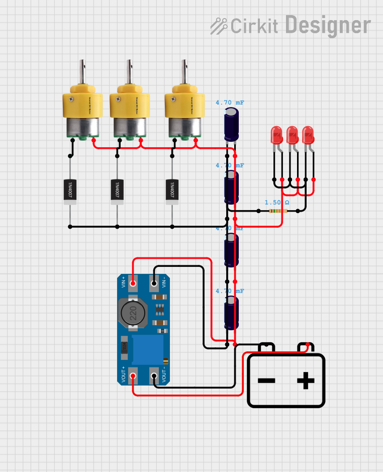
This circuit consists of multiple Center Shaft Metal Geared Motors, 1N4007 Rectifier Diodes, red LEDs, Electrolytic Capacitors, a Resistor, an MT3608 DC-DC Step-Up Converter, and a 12V Battery. The circuit is designed to drive motors and LEDs, with power regulation provided by the MT3608 module and protection by the diodes and capacitors.
Component List
Center Shaft Metal Geared Motor
- Pins: +, -
- Description: A motor with a metal gear for increased torque.
- Purpose: Drives mechanical components.
1N4007 Rectifier Diode
- Pins: Cathode, Anode
- Description: A general-purpose rectifier diode.
- Purpose: Provides protection against reverse voltage.
LED: Two Pin (red)
- Pins: cathode, anode
- Description: A red light-emitting diode.
- Purpose: Provides visual indication.
Electrolytic Capacitor
- Pins: -, +
- Description: A capacitor with a capacitance of 0.0047 Farads.
- Purpose: Filters and smooths voltage.
Resistor
- Pins: pin1, pin2
- Description: A resistor with a resistance of 1.5 Ohms.
- Purpose: Limits current flow.
MT3608
- Pins: VOUT+, VIN+, VOUT-, VIN-
- Description: A DC-DC step-up converter.
- Purpose: Boosts the input voltage to a higher output voltage.
12V Battery
- Pins: -, +
- Description: A 12V power source.
- Purpose: Provides power to the circuit.
Wiring Details
Center Shaft Metal Geared Motor
Motor 1:
- + Pin: Connected to the + pin of multiple Electrolytic Capacitors, VIN+ of MT3608, and anode of multiple LEDs.
- - Pin: Connected to the Anode of a 1N4007 Rectifier Diode.
Motor 2:
- + Pin: Connected to the + pin of multiple Electrolytic Capacitors, VIN+ of MT3608, and anode of multiple LEDs.
- - Pin: Connected to the Anode of a 1N4007 Rectifier Diode.
Motor 3:
- + Pin: Connected to the + pin of multiple Electrolytic Capacitors, VIN+ of MT3608, and anode of multiple LEDs.
- - Pin: Connected to the Anode of a 1N4007 Rectifier Diode.
1N4007 Rectifier Diode
Diode 1:
- Anode: Connected to the - pin of a Center Shaft Metal Geared Motor.
- Cathode: Connected to the - pin of multiple Electrolytic Capacitors and pin1 of the Resistor.
Diode 2:
- Anode: Connected to the - pin of a Center Shaft Metal Geared Motor.
- Cathode: Connected to the - pin of multiple Electrolytic Capacitors and pin1 of the Resistor.
Diode 3:
- Anode: Connected to the - pin of a Center Shaft Metal Geared Motor.
- Cathode: Connected to the - pin of multiple Electrolytic Capacitors and pin1 of the Resistor.
LED: Two Pin (red)
LED 1:
- Anode: Connected to the + pin of multiple Electrolytic Capacitors, VIN+ of MT3608, and + pin of Center Shaft Metal Geared Motors.
- Cathode: Connected to pin2 of the Resistor.
LED 2:
- Anode: Connected to the + pin of multiple Electrolytic Capacitors, VIN+ of MT3608, and + pin of Center Shaft Metal Geared Motors.
- Cathode: Connected to pin2 of the Resistor.
LED 3:
- Anode: Connected to the + pin of multiple Electrolytic Capacitors, VIN+ of MT3608, and + pin of Center Shaft Metal Geared Motors.
- Cathode: Connected to pin2 of the Resistor.
Electrolytic Capacitor
Capacitor 1:
- + Pin: Connected to the + pin of Center Shaft Metal Geared Motors, VIN+ of MT3608, and anode of LEDs.
- - Pin: Connected to the - pin of other Electrolytic Capacitors, pin1 of the Resistor, and Cathode of 1N4007 Rectifier Diodes.
Capacitor 2:
- + Pin: Connected to the + pin of Center Shaft Metal Geared Motors, VIN+ of MT3608, and anode of LEDs.
- - Pin: Connected to the - pin of other Electrolytic Capacitors, pin1 of the Resistor, and Cathode of 1N4007 Rectifier Diodes.
Capacitor 3:
- + Pin: Connected to the + pin of Center Shaft Metal Geared Motors, VIN+ of MT3608, and anode of LEDs.
- - Pin: Connected to the - pin of other Electrolytic Capacitors, pin1 of the Resistor, and Cathode of 1N4007 Rectifier Diodes.
Capacitor 4:
- + Pin: Connected to the + pin of Center Shaft Metal Geared Motors, VIN+ of MT3608, and anode of LEDs.
- - Pin: Connected to the - pin of other Electrolytic Capacitors, pin1 of the Resistor, and Cathode of 1N4007 Rectifier Diodes.
Resistor
- Pin1: Connected to the - pin of multiple Electrolytic Capacitors and Cathode of 1N4007 Rectifier Diodes.
- Pin2: Connected to the cathode of LEDs.
MT3608
- VIN+: Connected to the + pin of multiple Electrolytic Capacitors, + pin of Center Shaft Metal Geared Motors, and anode of LEDs.
- VIN-: Connected to the - pin of multiple Electrolytic Capacitors and pin1 of the Resistor.
- VOUT+: Connected to the + pin of the 12V Battery.
- VOUT-: Connected to the - pin of the 12V Battery.
12V Battery
- + Pin: Connected to VOUT+ of MT3608.
- - Pin: Connected to VOUT- of MT3608.
Code
No microcontroller code is provided for this circuit.