Cirkit Designer
Your all-in-one circuit design IDE
Home /
Project Documentation
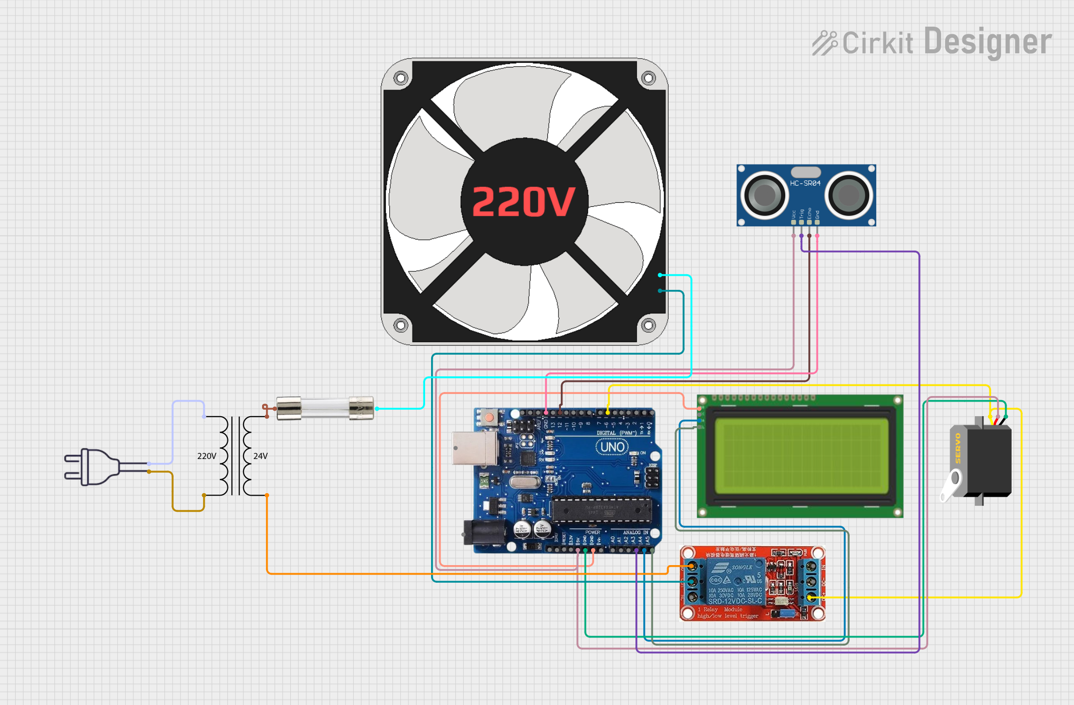
Ultrasonic Distance Measurement with Servo Control and LCD Display
Circuit Documentation
Summary
This circuit integrates an Arduino Uno R3 microcontroller with various components including ultrasonic sensors, a servo motor, an LCD display, a relay, and a fan. The primary function of the circuit is to measure distance using the HC-SR04 ultrasonic sensor, display the measured distance on the LCD, and control the position of a servo motor based on the distance measured. Additionally, the circuit includes a relay to control a 220V fan based on certain conditions.
Component List
Arduino Uno R3
- Description: A microcontroller board based on the ATmega328P.
- Purpose: Acts as the central control unit for the circuit, processing inputs from the ultrasonic sensor and controlling the servo motor and LCD display.
Servo
- Description: A small motor that can be controlled to rotate to a specific angle.
- Purpose: Adjusts its position based on the distance measured by the ultrasonic sensor.
HC-SR04 Ultrasonic Sensor
- Description: A distance measuring sensor that uses ultrasonic waves.
- Purpose: Measures the distance to an object and provides this data to the Arduino.
220 Fan
- Description: An electric fan powered by 220V AC.
- Purpose: Provides cooling; controlled via a relay.
Lcd 20x4 I2C
- Description: A 20x4 character LCD display with I2C interface.
- Purpose: Displays the distance measured by the ultrasonic sensor.
Power Transformer (220V to 24V)
- Description: A transformer that converts 220V AC to 24V AC.
- Purpose: Supplies power to the relay and fan.
12V Relay
- Description: An electromechanical switch that can control high voltage devices.
- Purpose: Controls the operation of the 220V fan based on signals from the Arduino.
Fuse
- Description: A safety device that protects the circuit from overcurrent.
- Purpose: Prevents damage to components by breaking the circuit in case of excessive current.
Power 220V
- Description: The main power supply for the circuit.
- Purpose: Provides the necessary voltage for the fan and relay operation.
Wiring Details
Arduino Uno R3
- 5V connected to Servo VCC
- GND connected to Servo GND
- GND connected to HC-SR04 GND
- A3 connected to HC-SR04 TRIG
- A4/SDA connected to LCD SCA
- A5/SCL connected to LCD SCL
- 12 connected to HC-SR04 ECHO
- 6 connected to Servo PULSE
- GND connected to LCD GND
Servo
- VCC connected to Arduino 5V
- GND connected to Arduino GND
- PULSE connected to Arduino pin 6
HC-SR04 Ultrasonic Sensor
- VCC connected to Arduino 5V
- GND connected to Arduino GND
- TRIG connected to Arduino pin A3
- ECHO connected to Arduino pin 12
220 Fan
- N connected to Relay COM
- L connected to Fuse Terminal 2
Lcd 20x4 I2C
- GND connected to Arduino GND
- 5V connected to Arduino 5V
- SCA connected to Arduino A4/SDA
- SCL connected to Arduino A5/SCL
Power Transformer (220V to 24V)
- 2 - Primary connected to Power 220V hot wire
- 1 - Primary connected to Power 220V neutral wire
- 3 - Secondary connected to Fuse Terminal 1
- 4 - Secondary connected to Relay NO
12V Relay
- DC+ connected to Arduino 5V
- DC- connected to Arduino GND
- COM connected to Fan N
- NO connected to Fan L
Fuse
- Terminal 1 connected to Transformer Secondary 3
- Terminal 2 connected to Fan L
Documented Code
Arduino Uno R3 Code
void setup() {
  // put your setup code here, to run once:

}

void loop() {
  // put your main code here, to run repeatedly:

}
HC-SR04 Ultrasonic Sensor Code
/*
 * This Arduino Sketch controls an HC-SR04 Ultrasonic Sensor, a Servo motor,
 * and an LCD display. The sensor measures the distance to an object, the
 * distance is displayed on the LCD, and the Servo motor rotates based on
 * the measured distance.
 */

#include <Wire.h>
#include <LiquidCrystal_I2C.h>
#include <Servo.h>

#define TRIG_PIN A3
#define ECHO_PIN 12
#define SERVO_PIN 6

LiquidCrystal_I2C lcd(0x27, 20, 4);
Servo myServo;

void setup() {
  lcd.begin();
  lcd.backlight();
  myServo.attach(SERVO_PIN);
  pinMode(TRIG_PIN, OUTPUT);
  pinMode(ECHO_PIN, INPUT);
}

void loop() {
  long duration, distance;
  digitalWrite(TRIG_PIN, LOW);
  delayMicroseconds(2);
  digitalWrite(TRIG_PIN, HIGH);
  delayMicroseconds(10);
  digitalWrite(TRIG_PIN, LOW);
  duration = pulseIn(ECHO_PIN, HIGH);
  distance = (duration / 2) / 29.1;
  lcd.setCursor(0, 0);
  lcd.print("Distance: ");
  lcd.print(distance);
  lcd.print(" cm");
  int angle = map(distance, 0, 100, 0, 180);
  myServo.write(angle);
  delay(500);
}
This documentation provides a comprehensive overview of the circuit, detailing each component, its purpose, wiring connections, and the code used to control the system.