
ESP32-Based Smart Home Automation System with Motion Detection and Environmental Monitoring
View and Edit Project In Cirkit Designer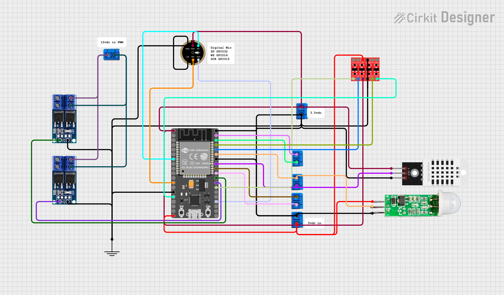
Circuit Documentation
Summary
This document provides a detailed overview of a circuit design that includes various components such as a HiLetGo ESP-32 microcontroller, motor drivers, sensors, and other peripheral devices. The circuit is designed to interface multiple sensors and actuators with the ESP-32 microcontroller, enabling complex control and monitoring functionalities.
Component List
Below is a list of components used in the circuit along with their descriptions and pin configurations.
Terminal PCB 2 Pin
- Description: General-purpose terminal block for connecting wires.
- Pins: Pin A, Pin B
Motor Driver - N-Mos PWM Trigger
- Description: Motor driver module for controlling motors using PWM signals.
- Pins: + PWM, GND, OUT -, OUT +, DC OUT +, DC IN -
GND
- Description: Ground connection point.
- Pins: GND
INMP441 FRONT MIC
- Description: Digital microphone module.
- Pins: L/R, WS, SCK, SD, VDD, GND
HiLetGo ESP-32
- Description: ESP-32 microcontroller module with multiple GPIO pins.
- Pins: 3.3, EN, GPIO36, GPIO39, GPIO34, GPIO35, GPIO32, GPIO33, GPIO25, GPIO26, GPIO27, GPIO14, GPIO12, GND, GPIO13, GPIO9, GPIO10, GPIO11, VIN, GPIO6, GPIO7, GPIO8, GPIO15, GPIO2, GPIO0, GPIO4, GPIO16, GPIO17, GPIO5, GPIO18, GPIO19, GPIO21, GPIO3, GPIO1, GPIO22, GPIO23
DHT22
- Description: Temperature and humidity sensor.
- Pins: +, Out, -
HC-SR505 Mini PIR Motion Sensing Module
- Description: Mini PIR motion sensor module.
- Pins: +, out, -
Bi-Directional Logic Level Converter
- Description: Logic level converter for interfacing different voltage levels.
- Pins: HV1, HV2, HV, GND, HV3, HV4, LV1, LV2, LV, LV3, LV4
Wiring Details
This section provides detailed wiring information for each component in the circuit.
Terminal PCB 2 Pin
Pin A is connected to:
- GPIO18 of HiLetGo ESP-32
- Pin A of another Terminal PCB 2 Pin
- VDD of INMP441 FRONT MIC
- LV of Bi-Directional Logic Level Converter
- 3.3 of HiLetGo ESP-32
-
- of DHT22
Pin B is connected to:
- GND of HC-SR505 Mini PIR Motion Sensing Module
- GND of GND
- L/R of INMP441 FRONT MIC
- GND of INMP441 FRONT MIC
- GND of Motor Driver - N-Mos PWM Trigger
- GND of another Motor Driver - N-Mos PWM Trigger
- GND of Bi-Directional Logic Level Converter
- GND of another Bi-Directional Logic Level Converter
- GND of HiLetGo ESP-32
- GND of another HiLetGo ESP-32
- GND of another HiLetGo ESP-32
-
- of DHT22
- HV of Bi-Directional Logic Level Converter
- VIN of HiLetGo ESP-32
- GPIO5 of HiLetGo ESP-32
- GPIO19 of HiLetGo ESP-32
- Out of DHT22
- GPIO22 of HiLetGo ESP-32
Motor Driver - N-Mos PWM Trigger
+ PWM is connected to:
- GPIO16 of HiLetGo ESP-32
- GPIO17 of HiLetGo ESP-32
GND is connected to:
- GND of GND
- GND of another Motor Driver - N-Mos PWM Trigger
DC OUT + is connected to:
- DC OUT + of another Motor Driver - N-Mos PWM Trigger
- Pin A of Terminal PCB 2 Pin
DC IN - is connected to:
- DC IN - of another Motor Driver - N-Mos PWM Trigger
- Pin B of Terminal PCB 2 Pin
GND
- GND is connected to:
- GND of HC-SR505 Mini PIR Motion Sensing Module
- Pin B of Terminal PCB 2 Pin
- L/R of INMP441 FRONT MIC
- GND of INMP441 FRONT MIC
- GND of Motor Driver - N-Mos PWM Trigger
- GND of another Motor Driver - N-Mos PWM Trigger
- GND of Bi-Directional Logic Level Converter
- GND of another Bi-Directional Logic Level Converter
- GND of HiLetGo ESP-32
- GND of another HiLetGo ESP-32
- GND of another HiLetGo ESP-32
-
- of DHT22
INMP441 FRONT MIC
L/R is connected to:
- GND of GND
WS is connected to:
- GPIO14 of HiLetGo ESP-32
SCK is connected to:
- GPIO15 of HiLetGo ESP-32
SD is connected to:
- GPIO32 of HiLetGo ESP-32
VDD is connected to:
- Pin A of Terminal PCB 2 Pin
GND is connected to:
- GND of GND
HiLetGo ESP-32
3.3 is connected to:
- LV of Bi-Directional Logic Level Converter
- Pin A of Terminal PCB 2 Pin
VIN is connected to:
- HV of Bi-Directional Logic Level Converter
- Pin B of Terminal PCB 2 Pin
GPIO18 is connected to:
- Pin A of Terminal PCB 2 Pin
GPIO16 is connected to:
-
- PWM of Motor Driver - N-Mos PWM Trigger
-
GPIO17 is connected to:
-
- PWM of another Motor Driver - N-Mos PWM Trigger
-
GPIO21 is connected to:
- out of HC-SR505 Mini PIR Motion Sensing Module
GPIO19 is connected to:
- Pin B of Terminal PCB 2 Pin
- Out of DHT22
GPIO23 is connected to:
- Pin A of Terminal PCB 2 Pin
GPIO22 is connected to:
- Pin B of Terminal PCB 2 Pin
GPIO14 is connected to:
- WS of INMP441 FRONT MIC
GPIO15 is connected to:
- SCK of INMP441 FRONT MIC
GPIO32 is connected to:
- SD of INMP441 FRONT MIC
GPIO13 is connected to:
- LV4 of Bi-Directional Logic Level Converter
GPIO4 is connected to:
- LV1 of Bi-Directional Logic Level Converter
GPIO3 is connected to:
- LV2 of Bi-Directional Logic Level Converter
GPIO1 is connected to:
- LV3 of Bi-Directional Logic Level Converter
DHT22
+ is connected to:
- Pin A of Terminal PCB 2 Pin
Out is connected to:
- GPIO19 of HiLetGo ESP-32
- Pin B of Terminal PCB 2 Pin
- is connected to:
- GND of GND
HC-SR505 Mini PIR Motion Sensing Module
+ is connected to:
- HV of Bi-Directional Logic Level Converter
- Pin B of Terminal PCB 2 Pin
out is connected to:
- GPIO21 of HiLetGo ESP-32
- Pin A of Terminal PCB 2 Pin
- is connected to:
- GND of GND
Bi-Directional Logic Level Converter
HV is connected to:
-
- of HC-SR505 Mini PIR Motion Sensing Module
- Pin B of Terminal PCB 2 Pin
- VIN of HiLetGo ESP-32
-
GND is connected to:
- GND of GND
- GND of another Bi-Directional Logic Level Converter
LV is connected to:
- 3.3 of HiLetGo ESP-32
- Pin A of Terminal PCB 2 Pin
LV4 is connected to:
- GPIO13 of HiLetGo ESP-32
LV1 is connected to:
- GPIO4 of HiLetGo ESP-32
LV2 is connected to:
- GPIO3 of HiLetGo ESP-32
LV3 is connected to:
- GPIO1 of HiLetGo ESP-32
Code
There is no code provided for the microcontrollers in this circuit.
This concludes the documentation for the circuit. If there are any questions or further clarifications needed, please feel free to reach out.