
ESP32-Controlled Automated Water Pump System with IR and Ultrasonic Sensors
View and Edit Project In Cirkit Designer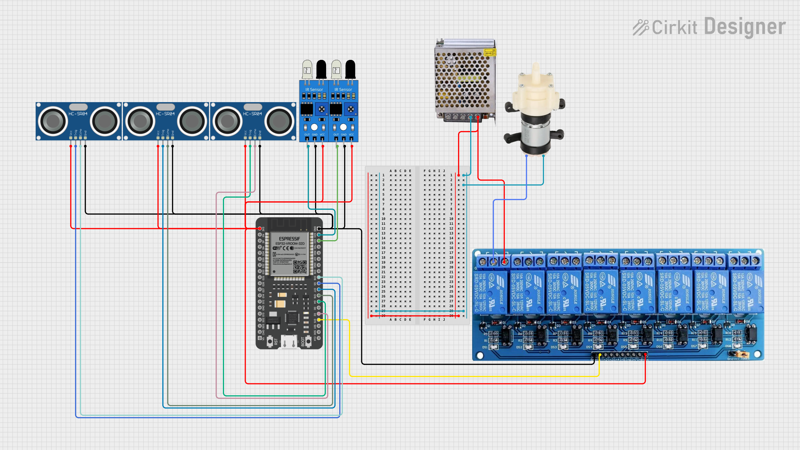
Circuit Documentation
Summary
This circuit is designed to interface an ESP32 microcontroller with a variety of sensors and actuators. The sensors include multiple HC-SR04 ultrasonic sensors and IR sensors for distance and object detection. The actuators in the circuit are a mini diaphragm water pump and a 5V 8-channel relay module, which is used to control the power supply to the pump. The power supply unit provides the necessary voltage levels for the different components in the circuit.
Component List
ESP32 - 38 pins
- Description: A microcontroller with WiFi and Bluetooth capabilities and a wide range of GPIO pins.
- Pins: 3V3, EN, SP, SN, G34, G35, G32, G33, G25, G26, G27, G14, G12, GND, G13, SD2, SD3, CMD, 5V, G23, G22, TXD, RXD, G21, G19, G18, G5, G17, G16, G4, G0, G2, G15, SD1, SD0, CLK
Mini Diaphragm Water Pump
- Description: A small pump used for moving water.
- Pins: Positive (+), Negative (-)
5V 8-Channel Relay
- Description: A relay module capable of controlling up to 8 different devices.
- Pins: GND, IN1, IN2, IN3, IN4, IN5, IN6, IN7, IN8, VCC, NC, C, NO
IR Sensor
- Description: An infrared sensor used for object detection.
- Pins: out, gnd, vcc
HC-SR04 Ultrasonic Sensor
- Description: An ultrasonic sensor used for measuring distances.
- Pins: VCC, TRIG, ECHO, GND
POWER SUPPLY 12V 5AMP
- Description: A power supply unit that converts AC to 12V 5A DC.
- Pins: 220V Positive Pole (AC), 220V Negative Pole (AC), GND, GND (DC), 12V-24V Output (DC)
Wiring Details
ESP32 - 38 pins
- 3V3: Connected to VCC of relay module, ultrasonic sensors, and IR sensors.
- GND: Connected to GND of relay module, ultrasonic sensors, and IR sensors.
- G23: Connected to the output of one IR sensor.
- G22: Connected to the output of another IR sensor.
- G18: Connected to the ECHO pin of one HC-SR04 ultrasonic sensor.
- G5: Connected to the TRIG pin of the same HC-SR04 ultrasonic sensor.
- G17: Connected to the TRIG pin of another HC-SR04 ultrasonic sensor.
- G16: Connected to the ECHO pin of that HC-SR04 ultrasonic sensor.
- G4: Connected to the TRIG pin of the third HC-SR04 ultrasonic sensor.
- G2: Connected to the ECHO pin of the third HC-SR04 ultrasonic sensor.
- G15: Connected to IN1 of the relay module.
Mini Diaphragm Water Pump
- Positive (+): Connected to the C (Common) pin of the relay module.
- Negative (-): Connected to GND (DC) of the power supply.
5V 8-Channel Relay
- VCC: Connected to 3V3 of ESP32.
- GND: Connected to GND of ESP32.
- IN1: Controlled by G15 of ESP32.
- NO: Connected to 12V-24V Output (DC) of the power supply.
- C: Connected to Positive (+) of the mini diaphragm water pump.
IR Sensor
- vcc: Connected to 3V3 of ESP32.
- gnd: Connected to GND of ESP32.
- out: Connected to G23 or G22 of ESP32 (depending on the instance).
HC-SR04 Ultrasonic Sensor
- VCC: Connected to 3V3 of ESP32.
- GND: Connected to GND of ESP32.
- TRIG: Connected to G5, G17, or G4 of ESP32 (depending on the instance).
- ECHO: Connected to G18, G16, or G2 of ESP32 (depending on the instance).
POWER SUPPLY 12V 5AMP
- 12V-24V Output (DC): Connected to NO of the relay module.
- GND (DC): Connected to Negative (-) of the mini diaphragm water pump.
Documented Code
No code has been provided for the microcontrollers in the circuit. The documentation of the code would include details on how the ESP32 interfaces with the sensors and controls the relay module based on the sensor inputs. It would also include the setup and loop functions, initialization of pins, and the logic for reading sensor data and controlling the actuators. Since no code is available, this section remains empty.