Dual Solar Panel Powered Fan

Circuit Documentation
Summary of the Circuit
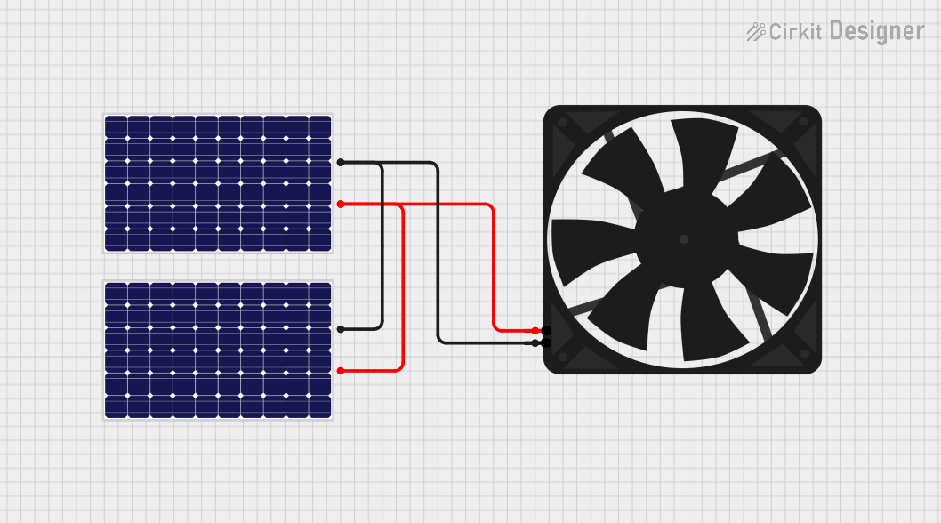
The circuit described by the provided inputs consists of two solar panels and one fan. The solar panels are used to generate electrical power from sunlight, which is then used to power the fan. The circuit is designed to connect the positive terminals of the solar panels to the 5V input of the fan, and the negative terminals of the solar panels to the ground (GND) of the fan. This setup suggests that the fan is intended to operate directly from the power supplied by the solar panels without any intermediate voltage regulation or energy storage components.
Component List
Fan
- Description: A fan component used for cooling or ventilation purposes.
- Pins:
- GND (Ground)
- 5V (Power Supply)
Solar Panel 1
- Description: A solar panel used to convert solar energy into electrical power.
- Pins:
- (Positive Terminal)
- (Negative Terminal)
Solar Panel 2
- Description: Another solar panel identical to Solar Panel 1, used to increase the power output by working in parallel with the first panel.
- Pins:
- (Positive Terminal)
- (Negative Terminal)
Wiring Details
Fan Wiring
- GND: Connected to the negative terminals of both Solar Panel 1 and Solar Panel 2.
- 5V: Connected to the positive terminals of both Solar Panel 1 and Solar Panel 2.
Solar Panel 1 Wiring
- + (Positive Terminal): Connected to the 5V pin of the Fan.
- - (Negative Terminal): Connected to the GND pin of the Fan.
Solar Panel 2 Wiring
- + (Positive Terminal): Connected to the 5V pin of the Fan.
- - (Negative Terminal): Connected to the GND pin of the Fan.
Documented Code
No microcontroller code was provided in the input. Therefore, there is no embedded code to document for this circuit. If in the future a microcontroller is added to the circuit, this section will be updated accordingly to include the code and its documentation.
This document provides an overview of the circuit's components, their purpose, and how they are interconnected. It should be used as a reference for understanding the circuit's design and for any troubleshooting or modifications that may be required.