
Arduino UNO Controlled Robotic Arm with Joystick and LCD Display
View and Edit Project In Cirkit Designer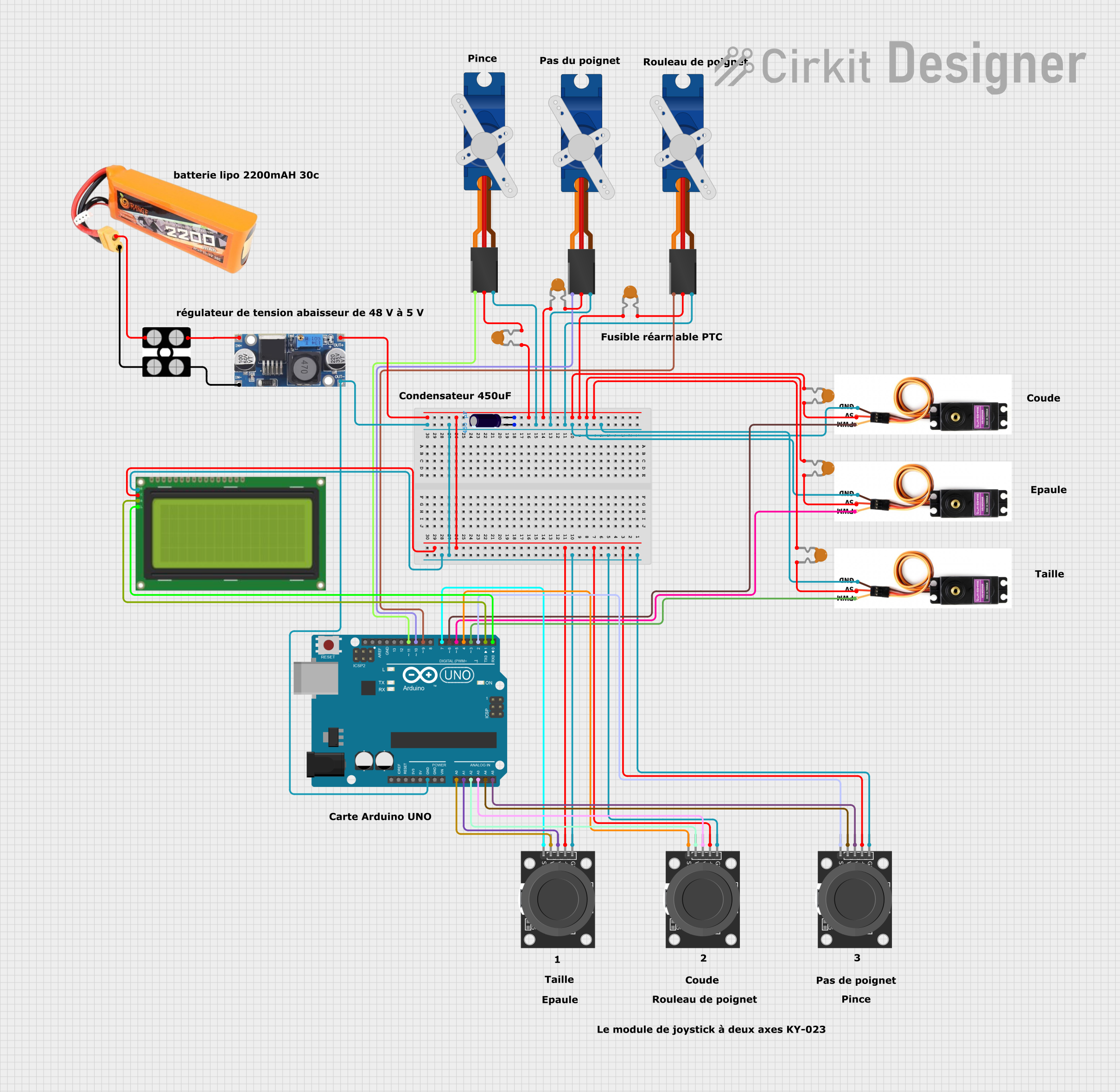
Circuit Documentation
Summary
This circuit is designed to control multiple servo motors using an Arduino UNO microcontroller. The system includes several joystick modules for user input, an LCD display for feedback, and a power supply system to ensure stable operation. The servos are controlled based on the joystick inputs, and the LCD displays the current joystick values.
Component List
Arduino UNO
- Description: Microcontroller board based on the ATmega328P.
- Pins: UNUSED, IOREF, Reset, 3.3V, 5V, GND, Vin, A0, A1, A2, A3, A4, A5, SCL, SDA, AREF, D13, D12, D11, D10, D9, D8, D7, D6, D5, D4, D3, D2, D1, D0
Electrolytic Capacitor
- Description: Capacitor used for smoothing voltage.
- Pins: -, +
- Properties: Capacitance: 0.00045 Farads
Tower Pro SG90 Servo
- Description: Small servo motor for precise control.
- Pins: Signal, +5V, GND
Servo Motor MG996R
- Description: High-torque servo motor.
- Pins: PMW, VCC 5V, GND
KY-023 Dual Axis Joystick Module
- Description: Joystick module for user input.
- Pins: GND, +5V, VRx, VRy, SW
Lipo Battery 2200mAH 30c
- Description: Rechargeable battery for power supply.
- Pins: VCC, GND
48v to 5v Converter
- Description: Voltage converter to step down from 48V to 5V.
- Pins: out+, out--, in+, in--
Resettable Fuse PTC
- Description: Fuse for overcurrent protection.
- Pins: 1, 2
Lcd 20x4 I2C
- Description: LCD display for visual feedback.
- Pins: GND, 5v, SCA, SCL
Wiring Details
Arduino UNO
- GND: Connected to GND of all other components.
- A0: Connected to VRy of KY-023 Dual Axis Joystick Module.
- A1: Connected to VRx of KY-023 Dual Axis Joystick Module.
- A2: Connected to VRy of another KY-023 Dual Axis Joystick Module.
- A3: Connected to VRx of another KY-023 Dual Axis Joystick Module.
- A4: Connected to VRy of another KY-023 Dual Axis Joystick Module.
- A5: Connected to VRx of another KY-023 Dual Axis Joystick Module.
- D11: Connected to Signal of Tower Pro SG90 Servo.
- D10: Connected to Signal of another Tower Pro SG90 Servo.
- D9: Connected to Signal of another Tower Pro SG90 Servo.
- D7: Connected to SW of KY-023 Dual Axis Joystick Module.
- D6: Connected to PMW of Servo Motor MG996R.
- D5: Connected to PMW of another Servo Motor MG996R.
- D4: Connected to SW of another KY-023 Dual Axis Joystick Module.
- D3: Connected to PMW of another Servo Motor MG996R.
- D2: Connected to SW of another KY-023 Dual Axis Joystick Module.
- D1: Connected to SCA of Lcd 20x4 I2C.
- D0: Connected to SCL of Lcd 20x4 I2C.
Electrolytic Capacitor
- -: Connected to GND.
- +: Connected to +5V.
Tower Pro SG90 Servo
- Signal: Connected to D11, D10, D9 of Arduino UNO.
- +5V: Connected to Resettable Fuse PTC.
- GND: Connected to GND.
Servo Motor MG996R
- PMW: Connected to D6, D5, D3 of Arduino UNO.
- VCC 5V: Connected to Resettable Fuse PTC.
- GND: Connected to GND.
KY-023 Dual Axis Joystick Module
- GND: Connected to GND.
- +5V: Connected to +5V.
- VRx: Connected to A1, A3, A5 of Arduino UNO.
- VRy: Connected to A0, A2, A4 of Arduino UNO.
- SW: Connected to D7, D4, D2 of Arduino UNO.
Lipo Battery 2200mAH 30c
- VCC: Connected to Domino.
- GND: Connected to Domino.
48v to 5v Converter
- in+: Connected to Domino.
- in--: Connected to Domino.
- out+: Connected to +5V.
- out--: Connected to GND.
Resettable Fuse PTC
- 1: Connected to +5V.
- 2: Connected to +5V of Tower Pro SG90 Servo and Servo Motor MG996R.
Lcd 20x4 I2C
- GND: Connected to GND.
- 5v: Connected to +5V.
- SCA: Connected to D1 of Arduino UNO.
- SCL: Connected to D0 of Arduino UNO.
Code Documentation
#include <Servo.h>
#include <Wire.h>
#include <LiquidCrystal_I2C.h>

// Déclaration des objets Servo
Servo servoTaille;
Servo servoEpaule;
Servo servoCoude;
Servo servoRouleauPoignet;
Servo servoPasPoignet;
Servo servoPince;

// Broches des servos
const int pinServoTaille = 2;
const int pinServoEpaule = 3;
const int pinServoCoude = 4;
const int pinServoRouleauPoignet = 5;
const int pinServoPasPoignet = 6;
const int pinServoPince = 7;

// Broches des joysticks
const int pinJoystick1X = A0;
const int pinJoystick1Y = A1;
const int pinJoystick2X = A2;
const int pinJoystick2Y = A3;
const int pinJoystick3X = A4;
const int pinJoystick3Y = A5;

// Déclaration de l'écran LCD I2C
LiquidCrystal_I2C lcd(0x27, 16, 2); // Adresse I2C de l'écran LCD (0x27 ou 0x3F) et taille de l'écran (16x2)

void setup() {
  // Initialiser l'écran LCD
  lcd.init();
  lcd.backlight();
  lcd.print("Initialisation...");
  delay(2000);
  lcd.clear();

  // Attacher les servos aux broches
  servoTaille.attach(pinServoTaille);
  servoEpaule.attach(pinServoEpaule);
  servoCoude.attach(pinServoCoude);
  servoRouleauPoignet.attach(pinServoRouleauPoignet);
  servoPasPoignet.attach(pinServoPasPoignet);
  servoPince.attach(pinServoPince);

  // Initialiser les servos à 90 degrés
  servoTaille.write(90);
  servoEpaule.write(90);
  servoCoude.write(90);
  servoRouleauPoignet.write(90);
  servoPasPoignet.write(90);
  servoPince.write(90);
}

void loop() {
  // Lire les valeurs des joysticks
  int valeurJoystick1X = analogRead(pinJoystick1X);
  int valeurJoystick1Y = analogRead(pinJoystick1Y);
  int valeurJoystick2X = analogRead(pinJoystick2X);
  int valeurJoystick2Y = analogRead(pinJoystick2Y);
  int valeurJoystick3X = analogRead(pinJoystick3X);
  int valeurJoystick3Y = analogRead(pinJoystick3Y);

  // Mapper les valeurs des joysticks à des angles de servo
  int angleTaille = map(valeurJoystick1X, 0, 1023, 0, 180);
  int angleEpaule = map(valeurJoystick1Y, 0, 1023, 0, 180);
  int angleCoude = map(valeurJoystick2X, 0, 1023, 0, 180);
  int angleRouleauPoignet = map(valeurJoystick2Y, 0, 1023, 0, 180);
  int anglePasPoignet = map(valeurJoystick3X, 0, 1023, 0, 180);
  int anglePince = map(valeurJoystick3Y, 0, 1023, 0, 180);

  // Écrire les angles aux servos
  servoTaille.write(angleTaille);
  servoEpaule.write(angleEpaule);
  servoCoude.write(angleCoude);
  servoRouleauPoignet.write(angleRouleauPoignet);