
Arduino-Controlled Bipolar Stepper Motor with Environmental Sensing
View and Edit Project In Cirkit Designer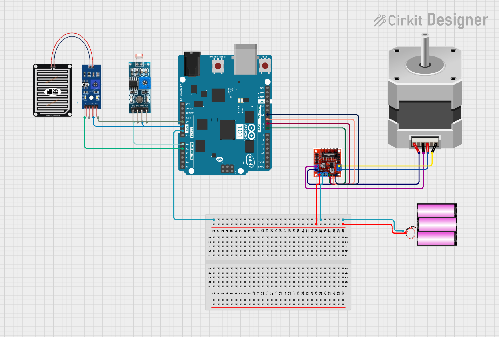
Circuit Documentation
Summary
This circuit is designed to control a bipolar stepper motor using an Arduino 101 microcontroller and an L298N Motor Driver Controller Board Module. The circuit also includes a 12V battery to power the motor driver and the stepper motor, as well as two sensors: a Module LDR (Light Dependent Resistor) and a RAIN SENSOR, both interfaced with the Arduino for environmental input.
Component List
Arduino 101
- Microcontroller board based on the Intel Curie Module
- Digital I/O Pins: 14 (of which 6 provide PWM output)
- Analog Input Pins: 6
- Operating Voltage: 3.3V
- Input Voltage (recommended): 7-12V
- Input Voltage (limit): 6-20V
Battery 12V
- Power source for the motor driver and stepper motor
- Voltage: 12V
Stepper Motor (Bipolar)
- A bipolar stepper motor with four leads
- Controlled by the L298N motor driver
L298N Motor Driver Controller Board Module
- Dual H-Bridge motor driver for DC or stepper motors
- Operating Voltage: Up to 35V DC
- Output Current: 2A per channel or 4A max
Module LDR
- Light sensor module with both digital and analog outputs
- Operating Voltage: Typically 3.3-5V
RAIN SENSOR
- Environmental sensor for detecting rain
- Operating Voltage: Typically 3.3-5V
Wiring Details
Arduino 101
GNDconnected to the ground of the battery and L298N Motor Driver's ground5Vconnected to VCC of RAIN SENSOR and Module LDRA0connected to AO of Module LDRA1connected to AO of RAIN SENSORD8connected to Input 1 of L298N Motor DriverD9 PWMconnected to Input 2 of L298N Motor DriverD10 PWM/SSconnected to Input 3 of L298N Motor DriverD11 PWM/MOSIconnected to Input 4 of L298N Motor Driver
Battery 12V
+connected to the +12v Power of L298N Motor Driver-connected to the ground of the Arduino 101 and L298N Motor Driver
Stepper Motor (Bipolar)
Aconnected to Output A of L298N Motor DriverBconnected to Output B of L298N Motor DriverCconnected to Output A of L298N Motor DriverDconnected to Output B of L298N Motor Driver
L298N Motor Driver Controller Board Module
+12v Powerconnected to the positive terminal of the batteryGroundconnected to the ground of the Arduino 101 and batteryOutput Aconnected to pins A and C of the Stepper MotorOutput Bconnected to pins B and D of the Stepper MotorInput 1connected to D8 of Arduino 101Input 2connected to D9 PWM of Arduino 101Input 3connected to D10 PWM/SS of Arduino 101Input 4connected to D11 PWM/MOSI of Arduino 101
Module LDR
VCCconnected to 5V of Arduino 101GNDconnected to GND of Arduino 101AOconnected to A0 of Arduino 101
RAIN SENSOR
VCCconnected to 5V of Arduino 101GRDconnected to GND of Arduino 101AOconnected to A1 of Arduino 101
Documented Code
#include <Stepper.h>

const int stepsPerPerRevotution = 200;
Stepper myStepper(stepsPerPerRevotution, 8, 9, 10, 11);

void setup() {
  myStepper.setSpeed(60);
  Serial.begin(9600);
}

void loop() {
  Serial.println("clockwise");
  myStepper.step(stepsPerPerRevotution);
  delay(500);

  Serial.println("counterclockwise");
  myStepper.step(-stepsPerPerRevotution);
  delay(500);
}
Code Description
- The code is written for the Arduino 101 microcontroller to control a bipolar stepper motor via the L298N Motor Driver.
- It includes the
Stepperlibrary, which is used to interface with stepper motors. - The
stepsPerPerRevotutionvariable defines the number of steps per revolution for the motor. - The
StepperobjectmyStepperis initialized with the number of steps and the pins connected to the motor driver inputs. - In the
setup()function, the stepper motor's speed is set, and the serial communication is started. - The
loop()function rotates the motor clockwise and counterclockwise with a delay between each rotation, and it sends messages to the serial monitor indicating the direction of rotation.