Cirkit Designer
Your all-in-one circuit design IDE
Home /
Project Documentation
Arduino UNO-Based Voltage Monitoring System with SMS Alerts via SIM800L
Circuit Documentation
Summary
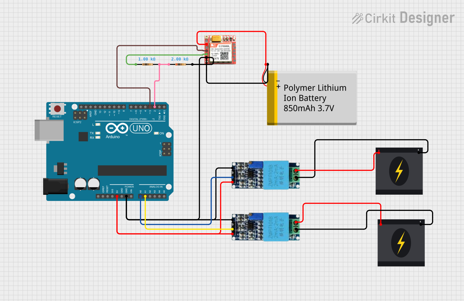
This circuit is designed to monitor voltage levels using two voltage sensors and an Arduino UNO microcontroller. When a voltage level exceeding a predefined threshold is detected, the Arduino UNO sends an SMS alert via the SIM800L GSM module. The circuit is powered by a Polymer Lithium Ion Battery and interfaces with a 240V AC power source through the voltage sensors.
Component List
Arduino UNO
- Microcontroller board based on the ATmega328P
- It has 14 digital input/output pins, 6 analog inputs, a 16 MHz quartz crystal, a USB connection, a power jack, an ICSP header, and a reset button.
Voltage Sensor (x2)
- A device that can measure the electrical voltage between two points in an electric circuit.
- It has pins for ground, phase, Vcc, output, and ground.
SIM800L
- A GSM/GPRS module that can provide a range of GSM functionalities.
- It has pins for network status, ringing indicator, power supply, data terminal ready, reset, microphone input/output, serial communication, and speaker output.
240V Power Source (x2)
- Provides a 240V AC power supply.
- It has pins for live and neutral.
Resistor (x2)
- A passive two-terminal electrical component that implements electrical resistance as a circuit element.
- One resistor has a resistance of 1000 Ohms, and the other has a resistance of 2000 Ohms.
Polymer Lithium Ion Battery - 850mAh
- A rechargeable battery of Lithium-ion technology.
- It has pins for ground and Vcc.
Wiring Details
Arduino UNO
5Vpin is connected to the Vcc pins of both Voltage Sensors.GNDpin is connected to the common ground network.A0pin is connected to the output of one Voltage Sensor.A1pin is connected to the output of the other Voltage Sensor.D2pin is connected to a 2000 Ohm Resistor.D3pin is connected to the RXD pin of the SIM800L module.
Voltage Sensors
Vccpins are connected to the 5V output from the Arduino UNO.Groundpins are connected to the neutral wire of the 240V Power Sources.Phasepins are connected to the live wire of the 240V Power Sources.Outpins are connected to the A0 and A1 pins on the Arduino UNO for voltage sensing.Gndpins are part of the common ground network.
SIM800L
VCCpin is connected to the VCC pin of the Polymer Lithium Ion Battery.GNDpin is part of the common ground network.RXDpin is connected to the D3 pin on the Arduino UNO.TXDpin is connected to a 1000 Ohm Resistor.
240V Power Sources
Livepins are connected to thePhasepins of the Voltage Sensors.Neutralpins are connected to theGroundpins of the Voltage Sensors.
Resistors
- One 1000 Ohm Resistor is connected between the TXD pin of the SIM800L and the common ground network.
- One 2000 Ohm Resistor is connected between the D2 pin of the Arduino UNO and the common ground network.
Polymer Lithium Ion Battery - 850mAh
VCCpin is connected to the VCC pin of the SIM800L module.GNDpin is part of the common ground network.
Documented Code
/*
 * This Arduino Sketch reads voltage levels from two voltage sensors connected to
 * analog pins A0 and A1. If the voltage level exceeds 10V, it sends an SMS
 * message indicating which sensor detected the voltage using the SIM800L module.
 */

#include <SoftwareSerial.h>

// Define pins
const int sensor1Pin = A0;
const int sensor2Pin = A1;
const int sim800lTxPin = 2;
const int sim800lRxPin = 3;

// Threshold voltage in analogRead units (10V / 5V * 1023)
const int threshold = 204;

// Phone number to send SMS
const char phoneNumber[] = "+237671693917";

// Create a SoftwareSerial object for SIM800L
SoftwareSerial sim800l(sim800lRxPin, sim800lTxPin);

void setup() {
  // Initialize serial communication
  Serial.begin(9600);
  sim800l.begin(9600);

  // Wait for SIM800L to initialize
  delay(1000);

  // Send initial AT command to check communication
  sim800l.println("AT");
  delay(1000);
}

void loop() {
  // Read voltage levels from sensors
  int sensor1Value = analogRead(sensor1Pin);
  int sensor2Value = analogRead(sensor2Pin);

  // Check if sensor1 detects voltage above threshold
  bool sensor1Active = sensor1Value > threshold;
  bool sensor2Active = sensor2Value > threshold;

  if (sensor1Active && sensor2Active) {
    sendSMS("ACTIVE 1 and ACTIVE 2");
  } else {
    if (sensor1Active) {
      sendSMS("ACTIVE 1");
    }
    if (sensor2Active) {
      sendSMS("ACTIVE 2");
    }
  }

  // Wait for a while before next reading
  delay(5000);
}

void sendSMS(const char* message) {
  // Send AT command to set SMS mode to text
  sim800l.println("AT+CMGF=1");
  delay(1000);

  // Send AT command to set recipient phone number
  sim800l.print("AT+CMGS=\"");
  sim800l.print(phoneNumber);
  sim800l.println("\"");
  delay(1000);

  // Send the message
  sim800l.println(message);
  delay(1000);

  // Send Ctrl+Z to indicate end of message
  sim800l.write(26);
  delay(1000);
}
This code is responsible for reading the voltage levels from the sensors and sending an SMS alert when the voltage exceeds the threshold. It uses the SoftwareSerial library to communicate with the SIM800L module. The sendSMS function handles the process of sending an SMS message to a predefined phone number.