
Arduino UNO-Based IR LED Control and Keypad Input with LCD Display
View and Edit Project In Cirkit Designer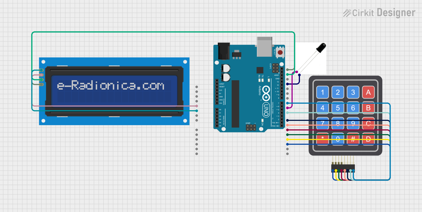
Circuit Documentation
Summary
This circuit involves an Arduino UNO microcontroller interfacing with an IR LED, a 4x4 Keypad, and a 16x2 I2C LCD screen. The Arduino UNO controls the IR LED, reads input from the keypad, and displays messages on the LCD screen. The circuit is designed to demonstrate basic input and output operations using these components.
Component List
Arduino UNO
- Description: A microcontroller board based on the ATmega328P.
- Pins: UNUSED, IOREF, Reset, 3.3V, 5V, GND, Vin, A0, A1, A2, A3, A4, A5, SCL, SDA, AREF, D13, D12, D11, D10, D9, D8, D7, D6, D5, D4, D3, D2, D1, D0
IR LED
- Description: An infrared light-emitting diode.
- Pins: GND, VCC
4x4 Keypad (Simulator)
- Description: A 4x4 matrix keypad used for user input.
- Pins: R1, C4, R2, C2, R3, R4, C1, C3
LCD screen 16x2 I2C
- Description: A 16x2 character LCD display with I2C interface.
- Pins: SCL, SDA, VCC, GND
Wiring Details
Arduino UNO
- 5V connected to VCC of the LCD screen 16x2 I2C
- GND connected to GND of the LCD screen 16x2 I2C
- SCL connected to SCL of the LCD screen 16x2 I2C
- SDA connected to SDA of the LCD screen 16x2 I2C
- GND connected to GND of the IR LED
- D10 connected to C4 of the 4x4 Keypad (Simulator)
- D9 connected to VCC of the IR LED
- D8 connected to C3 of the 4x4 Keypad (Simulator)
- D7 connected to C2 of the 4x4 Keypad (Simulator)
- D6 connected to C1 of the 4x4 Keypad (Simulator)
- D5 connected to R4 of the 4x4 Keypad (Simulator)
- D4 connected to R3 of the 4x4 Keypad (Simulator)
- D3 connected to R2 of the 4x4 Keypad (Simulator)
- D2 connected to R1 of the 4x4 Keypad (Simulator)
IR LED
- GND connected to GND of the Arduino UNO
- VCC connected to D9 of the Arduino UNO
4x4 Keypad (Simulator)
- C4 connected to D10 of the Arduino UNO
- C3 connected to D8 of the Arduino UNO
- C2 connected to D7 of the Arduino UNO
- C1 connected to D6 of the Arduino UNO
- R4 connected to D5 of the Arduino UNO
- R3 connected to D4 of the Arduino UNO
- R2 connected to D3 of the Arduino UNO
- R1 connected to D2 of the Arduino UNO
LCD screen 16x2 I2C
- VCC connected to 5V of the Arduino UNO
- GND connected to GND of the Arduino UNO
- SCL connected to SCL of the Arduino UNO
- SDA connected to SDA of the Arduino UNO
Code Documentation
Included Libraries
#include <Wire.h>
#include <LiquidCrystal_I2C.h>
#include <Keypad.h>
IR LED Control
Setup Function:
void setupIR() {
  pinMode(9, OUTPUT); // Initialize the digital pin as an output.
}
Loop Function:
void loopIR() {
  digitalWrite(9, HIGH); // Turn the IR LED on
  delay(1000); // Wait for a second
  digitalWrite(9, LOW); // Turn the IR LED off
  delay(1000); // Wait for a second
}
Keypad Input
Keypad Configuration:
const byte ROWS = 4; // Four rows
const byte COLS = 4; // Four columns
char keys[ROWS][COLS] = {
  {'1', '2', '3', 'A'},
  {'4', '5', '6', 'B'},
  {'7', '8', '9', 'C'},
  {'*', '0', '#', 'D'}
};
byte rowPins[ROWS] = {2, 3, 4, 5}; // Row pins
byte colPins[COLS] = {6, 7, 8, 10}; // Column pins
Keypad keypad = Keypad(makeKeymap(keys), rowPins, colPins, ROWS, COLS);
Setup Function:
void setupKeypad() {
  Serial.begin(9600);
}
Loop Function:
void loopKeypad() {
  char key = keypad.getKey();
  if (key) {
    Serial.println(key);
  }
}
LCD Display
LCD Configuration:
LiquidCrystal_I2C lcd(0x27, 16, 2); // Set the LCD address to 0x27
Setup Function:
void setupLCD() {
  lcd.init(); // Use init instead of begin
  lcd.backlight(); // Turn on the backlight
  lcd.setCursor(0, 0); // Set cursor to column 0, line 0
  lcd.print("Hello, World!"); // Print message
  lcd.setCursor(0, 1); // Set cursor to column 0, line 1
  lcd.print("LCD 16x2 I2C"); // Print message
}
Loop Function:
void loopLCD() {
  // LCD does not require continuous updates in the loop
}
Main Setup and Loop
Setup Function:
void setup() {
  setupIR();
  setupKeypad();
  setupLCD();
}
Loop Function:
void loop() {
  loopIR();
  loopKeypad();
  // loopLCD is not required since no dynamic updates are happening
}