
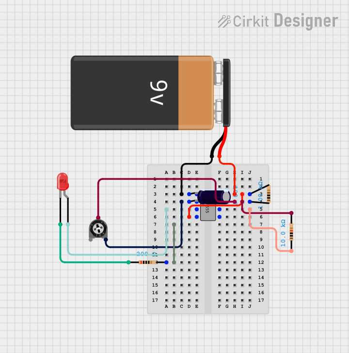
Circuit Documentation
Summary of the Circuit
This circuit appears to be a timer or oscillator circuit utilizing a 555 timer IC. The 555 timer is configured with external resistors, a trimmer potentiometer, and a capacitor to set the timing characteristics. An LED is included in the circuit, likely to provide a visual indication of the timer's output. The circuit is powered by a 9V battery.
Component List
555 Timer IC
- Description: A highly stable device for generating accurate time delays or oscillation.
- Pins: GND, TRIG, OUT, ~RESET, VCC, DIS, THR, CTRL
Electrolytic Capacitor
- Description: A polarized capacitor with a capacitance of 100 Farads.
- Properties: Capacitance: 100 Farads
Resistors
- Description: Passive electrical components providing resistance to the flow of electric current.
- Properties:
- Resistor 1: 1000 Ohms
- Resistor 2: 10000 Ohms
- Resistor 3: 200 Ohms
Trimmer Potentiometer
- Description: A three-terminal resistor with an adjustable center tap, providing a variable resistance.
- Properties: Resistance: 10000 Ohms
LED: Two Pin (red)
- Description: A red light-emitting diode used as an indicator.
- Pins: cathode, anode
9V Battery
- Description: A standard 9V battery providing power to the circuit.
Wiring Details
555 Timer IC
- GND connected to Electrolytic Capacitor (-) and 9V Battery (-)
- TRIG connected to Electrolytic Capacitor (+) and Trimmer Potentiometer (leg2)
- OUT connected to LED (anode)
- ~RESET connected to 9V Battery (+)
- VCC connected to 9V Battery (+) through Resistor 1 (1000 Ohms)
- DIS connected to Resistor 1 (1000 Ohms), Resistor 2 (10000 Ohms), and Trimmer Potentiometer (wiper)
- THR connected to Resistor 2 (10000 Ohms)
Electrolytic Capacitor
- (-) connected to 555 Timer IC (GND) and 9V Battery (-)
- (+) connected to 555 Timer IC (TRIG) and Trimmer Potentiometer (leg2)
Resistors
- Resistor 1 (1000 Ohms): One end connected to 555 Timer IC (VCC), other end to 555 Timer IC (DIS)
- Resistor 2 (10000 Ohms): One end connected to 555 Timer IC (DIS), other end to 555 Timer IC (THR)
- Resistor 3 (200 Ohms): One end connected to LED (cathode)
Trimmer Potentiometer
- leg1: Not connected
- wiper: Connected to 555 Timer IC (DIS)
- leg2: Connected to 555 Timer IC (TRIG) and Electrolytic Capacitor (+)
LED: Two Pin (red)
- cathode: Connected to Resistor 3 (200 Ohms)
- anode: Connected to 555 Timer IC (OUT)
9V Battery
- (-) connected to 555 Timer IC (GND) and Electrolytic Capacitor (-)
- (+) connected to 555 Timer IC (~RESET) and VCC through Resistor 1 (1000 Ohms)
Documented Code
No code has been provided for this circuit as there are no microcontrollers or programmable devices included in the provided list of components. The 555 timer IC operates based on its pin configurations and the values of the external components connected to it.