
Arduino UNO Keypad-Controlled LED and Buzzer System with RTC and Bluetooth
View and Edit Project In Cirkit Designer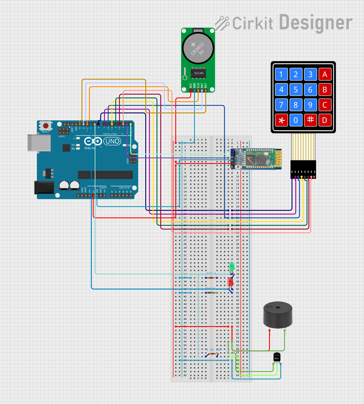
Circuit Documentation
Summary
This circuit is designed to interface a 4x4 membrane matrix keypad with an Arduino UNO. The circuit also includes a red and green LED, a buzzer, an RTC-DS1302 module, an HC-05 Bluetooth module, and an NPN transistor. The Arduino UNO reads the key pressed on the keypad and prints it to the serial monitor. The LEDs and buzzer provide visual and auditory feedback, respectively.
Component List
LED: Two Pin (red)
- Description: A red LED with two pins: cathode and anode.
- Purpose: Provides visual feedback.
4X4 Membrane Matrix Keypad
- Description: A 4x4 matrix keypad with 8 pins: R1, R2, R3, R4, C1, C2, C3, C4.
- Purpose: Allows user input.
Arduino UNO
- Description: A microcontroller board with multiple digital and analog I/O pins.
- Purpose: Central control unit for the circuit.
LED: Two Pin (green)
- Description: A green LED with two pins: cathode and anode.
- Purpose: Provides visual feedback.
Resistor (200 Ohms)
- Description: A resistor with a resistance of 200 Ohms.
- Purpose: Limits current to the LEDs.
Resistor (2000 Ohms)
- Description: A resistor with a resistance of 2000 Ohms.
- Purpose: Limits current in the transistor circuit.
Buzzer
- Description: A buzzer with two pins: PIN and GND.
- Purpose: Provides auditory feedback.
NPN-Transistor
- Description: An NPN transistor with three pins: E (Emitter), C (Collector), B (Base).
- Purpose: Controls the buzzer.
RTC-DS1302
- Description: A real-time clock module with five pins: Vcc, GND, CLK, DAT, RST.
- Purpose: Keeps track of time.
HC-05
- Description: A Bluetooth module with six pins: STATE, RXD, TXD, GND, VCC, EN.
- Purpose: Enables Bluetooth communication.
Wiring Details
LED: Two Pin (red)
- Anode: Connected to Arduino UNO pin D10.
- Cathode: Connected to one end of a 200 Ohm resistor.
- 200 Ohm Resistor (other end): Connected to GND.
4X4 Membrane Matrix Keypad
- R1: Connected to Arduino UNO pin D8.
- R2: Connected to Arduino UNO pin D7.
- R3: Connected to Arduino UNO pin D6.
- R4: Connected to Arduino UNO pin D5.
- C1: Connected to Arduino UNO pin D4.
- C2: Connected to Arduino UNO pin D3.
- C3: Connected to Arduino UNO pin D2.
- C4: Not connected.
Arduino UNO
- 5V: Connected to Vcc of RTC-DS1302, VCC of HC-05, and PIN of the buzzer.
- GND: Connected to GND of RTC-DS1302, GND of HC-05, pin1 of a 200 Ohm resistor, pin1 of another 200 Ohm resistor, and B of the NPN transistor.
- D0: Connected to RXD of HC-05.
- D1: Not connected.
- D8: Connected to R1 of the keypad.
- D7: Connected to R2 of the keypad.
- D6: Connected to R3 of the keypad.
- D5: Connected to R4 of the keypad.
- D4: Connected to C1 of the keypad.
- D3: Connected to C2 of the keypad.
- D2: Connected to C3 of the keypad.
- D9: Connected to the cathode of the green LED through a 2000 Ohm resistor.
- D10: Connected to the anode of the red LED.
- D11: Connected to CLK of RTC-DS1302.
- D12: Connected to DAT of RTC-DS1302.
- D13: Connected to RST of RTC-DS1302.
LED: Two Pin (green)
- Anode: Connected to one end of a 200 Ohm resistor.
- Cathode: Connected to Arduino UNO pin D9.
- 200 Ohm Resistor (other end): Connected to GND.
Buzzer
- PIN: Connected to Arduino UNO 5V.
- GND: Connected to E of the NPN transistor.
NPN-Transistor
- E: Connected to GND of the buzzer.
- C: Connected to one end of a 2000 Ohm resistor.
- B: Connected to GND.
RTC-DS1302
- Vcc: Connected to Arduino UNO 5V.
- GND: Connected to Arduino UNO GND.
- CLK: Connected to Arduino UNO pin D11.
- DAT: Connected to Arduino UNO pin D12.
- RST: Connected to Arduino UNO pin D13.
HC-05
- VCC: Connected to Arduino UNO 5V.
- GND: Connected to Arduino UNO GND.
- RXD: Connected to Arduino UNO pin D0.
- TXD: Not connected.
- STATE: Not connected.
- EN: Not connected.
Code Documentation
/*
 * This Arduino sketch interfaces with a 4x4 membrane matrix keypad.
 * The rows of the keypad are connected to digital pins 9, 8, 7, and 6.
 * The columns of the keypad are connected to digital pins 5, 4, 3, and 2.
 * The code reads the key pressed on the keypad and prints it to the serial monitor.
 */

#include <Keypad.h>

const byte ROWS = 4; // Four rows
const byte COLS = 4; // Four columns

// Define the keymap
char keys[ROWS][COLS] = {
  {'1','2','3','A'},
  {'4','5','6','B'},
  {'7','8','9','C'},
  {'*','0','#','D'}
};

// Connect keypad ROW0, ROW1, ROW2 and ROW3 to these Arduino pins.
byte rowPins[ROWS] = {9, 8, 7, 6};
// Connect keypad COL0, COL1, COL2 and COL3 to these Arduino pins.
byte colPins[COLS] = {5, 4, 3, 2};

// Create the Keypad
Keypad keypad = Keypad(makeKeymap(keys), rowPins, colPins, ROWS, COLS);

void setup() {
  Serial.begin(9600);
}

void loop() {
  char key = keypad.getKey();
  if (key) {
    Serial.println(key);
  }
}
This code initializes the keypad and sets up the serial communication. In the loop function, it continuously checks for key presses and prints the pressed key to the serial monitor.