
Arduino UNO Light-Activated Servo Control with Dual LDR Sensors
View and Edit Project In Cirkit Designer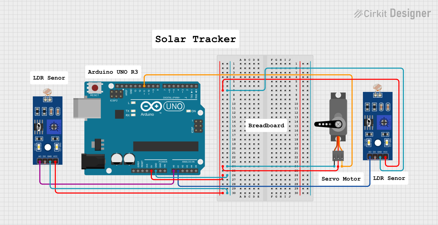
Circuit Documentation
Summary
This circuit involves an Arduino UNO microcontroller, two Light Dependent Resistors (LDRs), and a Servo motor. The Arduino UNO reads the analog values from the LDRs and controls the Servo motor based on these readings. The circuit is powered by the 5V supply from the Arduino UNO.
Component List
Arduino UNO
- Description: A microcontroller board based on the ATmega328P.
- Pins: UNUSED, IOREF, Reset, 3.3V, 5V, GND, Vin, A0, A1, A2, A3, A4, A5, SCL, SDA, AREF, D13, D12, D11, D10, D9, D8, D7, D6, D5, D4, D3, D2, D1, D0
LDR (Light Dependent Resistor)
- Description: A resistor whose resistance decreases with increasing incident light intensity.
- Pins: A0, D0, GND, VCC
Servo
- Description: A motor that can be controlled to move to a specific position.
- Pins: GND, VCC, PWM
Wiring Details
Arduino UNO
- 5V: Connected to VCC of both LDRs and the Servo.
- GND: Connected to GND of both LDRs and the Servo.
- A0: Connected to A0 of the first LDR.
- A1: Connected to A0 of the second LDR.
- D11: Connected to PWM of the Servo.
LDR (First)
- VCC: Connected to 5V of the Arduino UNO.
- GND: Connected to GND of the Arduino UNO.
- A0: Connected to A0 of the Arduino UNO.
LDR (Second)
- VCC: Connected to 5V of the Arduino UNO.
- GND: Connected to GND of the Arduino UNO.
- A0: Connected to A1 of the Arduino UNO.
Servo
- VCC: Connected to 5V of the Arduino UNO.
- GND: Connected to GND of the Arduino UNO.
- PWM: Connected to D11 of the Arduino UNO.
Code Documentation
Arduino UNO Code
File Name: sketch.ino
void setup() {
  // put your setup code here, to run once:

}

void loop() {
  // put your main code here, to run repeatedly:

}
File Name: documentation.txt
This code initializes the Arduino UNO but does not contain any specific logic for reading the LDRs or controlling the Servo. You can add your custom logic in the setup() and loop() functions.