
Arduino UNO RFID Access Control System with LCD Feedback and Buzzer Alerts
View and Edit Project In Cirkit Designer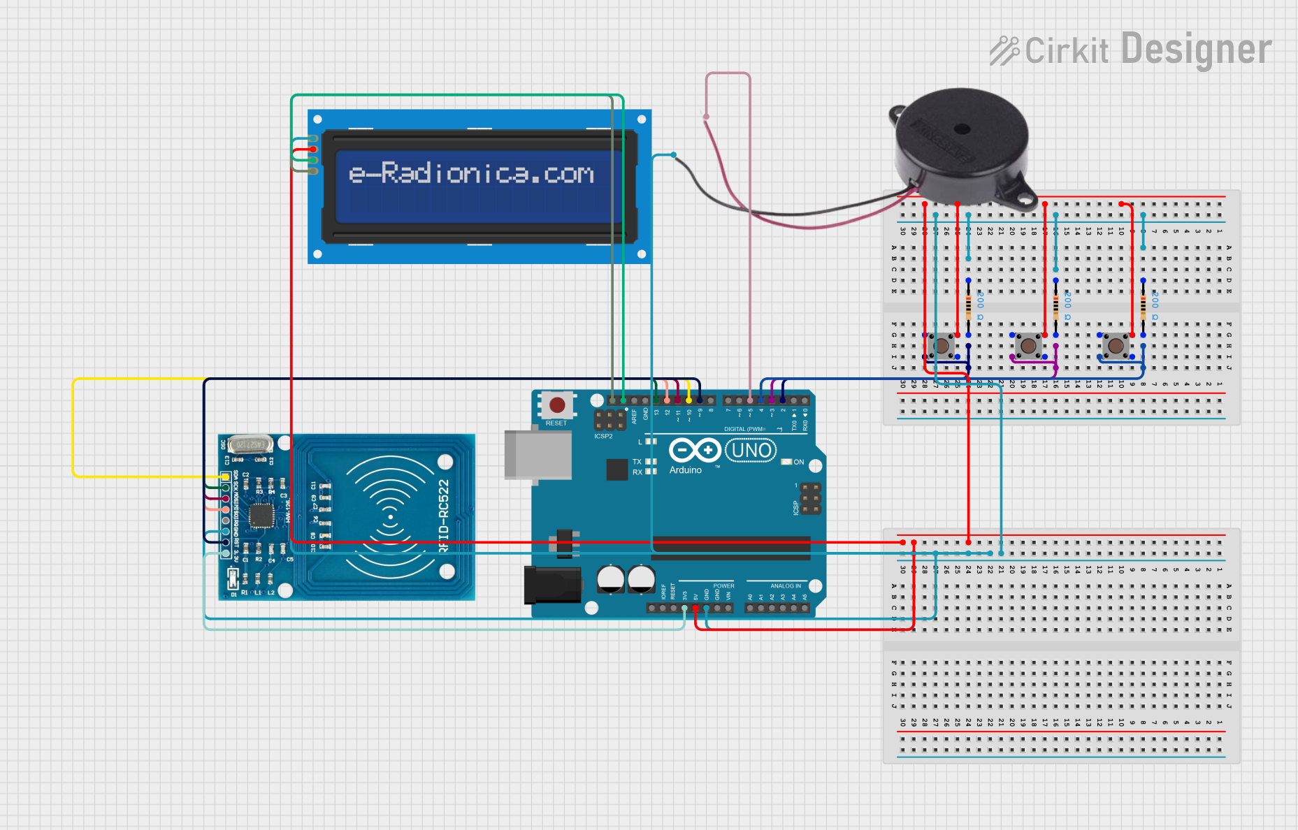
Circuit Documentation
Summary
This circuit incorporates a variety of components including pushbuttons, resistors, an Arduino UNO microcontroller, an LCD screen with I2C interface, a buzzer, and an RFID-RC522 module. The circuit is designed to interface with various input and output devices, likely for a user interface system with RFID capabilities. The Arduino UNO serves as the central processing unit, controlling the LCD display, reading RFID tags, and responding to button presses. The resistors are likely used for pull-up or pull-down configurations for the pushbuttons, and the buzzer provides audible feedback.
Component List
Pushbutton
- Description: A standard pushbutton with four pins, typically used as an input device to trigger events or actions.
- Pins: Pin 3 (out), Pin 4 (out), Pin 1 (in), Pin 2 (in)
Resistor
- Description: A passive two-terminal electrical component that implements electrical resistance as a circuit element.
- Resistance: 200 Ohms
Arduino UNO
- Description: A microcontroller board based on the ATmega328P, with a variety of digital and analog I/O pins.
- Pins: UNUSED, IOREF, Reset, 3.3V, 5V, GND, Vin, A0 to A5, SCL, SDA, AREF, D0 to D13
LCD screen 16x2 I2C
- Description: A 16x2 character LCD display with an I2C interface for displaying text and characters.
- Pins: SCL, SDA, VCC, GND
Buzzer
- Description: An electronic buzzer that produces sound when powered.
- Pins: POSITIVE, NEGATIVE
RFID-RC522
- Description: An RFID reader/writer module based on the MFRC522 chip, operating at 13.56 MHz.
- Pins: VCC (3.3V), RST, GND, IRQ, MISO, MOSI, SCK, SDA
Wiring Details
Pushbutton
- One side connected to the 5V supply through a resistor.
- The other side connected to a digital input pin on the Arduino UNO (D2, D3, or D4).
Resistor
- Connected between the pushbuttons and the 5V supply or ground.
- Acts as pull-up or pull-down resistors for the pushbuttons.
Arduino UNO
- GND pin connected to the ground net, which includes the negative side of the buzzer, GND of the LCD screen, and GND of the RFID-RC522.
- 5V pin provides power to the pushbuttons.
- 3.3V pin provides power to the RFID-RC522.
- Digital pins D2, D3, and D4 are connected to pushbuttons.
- Digital pins D5 controls the buzzer.
- Digital pins D9 to D13 are connected to the RFID-RC522.
- Analog pins A4 (SDA) and A5 (SCL) are connected to the I2C pins of the LCD screen.
LCD screen 16x2 I2C
- SCL and SDA pins connected to the corresponding SCL and SDA pins on the Arduino UNO.
- VCC connected to the 5V supply.
- GND connected to the ground net.
Buzzer
- POSITIVE pin connected to digital pin D5 on the Arduino UNO.
- NEGATIVE pin connected to the ground net.
RFID-RC522
- VCC (3.3V) connected to the 3.3V pin on the Arduino UNO.
- RST, MISO, MOSI, SCK, and SDA pins connected to digital pins D9 to D13 on the Arduino UNO.
- GND connected to the ground net.
Documented Code
void setup() {
  // put your setup code here, to run once:

}

void loop() {
  // put your main code here, to run repeatedly:

}
Filename: sketch.ino
The provided code is a template with empty setup() and loop() functions, which are the standard structure for Arduino sketches. The setup() function is intended for initialization code that runs once when the device is powered on or reset, while the loop() function contains code that runs continuously. Additional code would be required to implement the functionality for reading RFID tags, responding to button presses, controlling the LCD display, and activating the buzzer.