
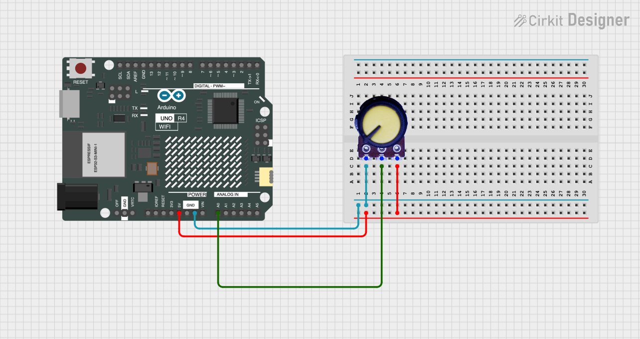
Circuit Documentation
Summary
The circuit in question consists of two primary components: a potentiometer and an Arduino UNO R4 WiFi microcontroller. The potentiometer is used as a variable resistor to provide an analog input to the Arduino. The Arduino UNO R4 WiFi is the central processing unit of the circuit, capable of executing programmed instructions and interfacing with various peripherals and sensors. The potentiometer's output is connected to one of the Arduino's analog inputs for reading its position. The ground and power supply pins of the potentiometer are connected to the corresponding pins on the Arduino to complete the circuit.
Component List
Potentiometer
- Pins: GND, Output, VCC
- Description: A three-terminal resistor with a sliding or rotating contact that forms an adjustable voltage divider. Used for adjusting a parameter or controlling a signal.
Arduino UNO R4 WiFi
- Pins: OFF, GND, VRTC, IIC0_SCL, IIC0_SDA, 3V3, GPIO 41, GPIO 0, GPIO 42, GPIO 43, GPIO 44, BOOT, IOREF, RESET, 5V, VIN, A0, A1, A2, A3, A4, A5, RSPCKA, CIPO, COPI, D0/RX, D1/TX, D2, D3, D4, D5, D6, D7, D8, D9, D10, D11, D12, D13, AREF, SDA, SCL
- Description: A microcontroller board based on the ATmega328P, with integrated WiFi capability. It has digital and analog I/O pins and is used for building digital devices and interactive objects that can sense and control objects in the physical and digital world.
Wiring Details
Potentiometer Wiring
- GND: Connected to the Arduino UNO R4 WiFi GND pin.
- Output: Connected to the Arduino UNO R4 WiFi A0 pin.
- VCC: Connected to the Arduino UNO R4 WiFi 5V pin.
Arduino UNO R4 WiFi Wiring
- GND: Connected to the Potentiometer GND pin.
- A0: Connected to the Potentiometer Output pin.
- 5V: Connected to the Potentiometer VCC pin.
Documented Code
Arduino UNO R4 WiFi Code (sketch.ino)
void setup() {
  // put your setup code here, to run once:

}

void loop() {
  // put your main code here, to run repeatedly:

}
Additional Notes
- The provided code for the Arduino UNO R4 WiFi is a template with empty
setup()andloop()functions. These functions are intended to be filled with user-defined code to initialize the microcontroller and define its behavior during operation. - The
setup()function is called once when the microcontroller is powered on or reset. It is typically used to initialize variables, pin modes, start using libraries, etc. - The
loop()function is called repeatedly and is used to execute the main logic of the program.