ESP32-Powered Piezo Sensor Interface System
Circuit Documentation
Summary
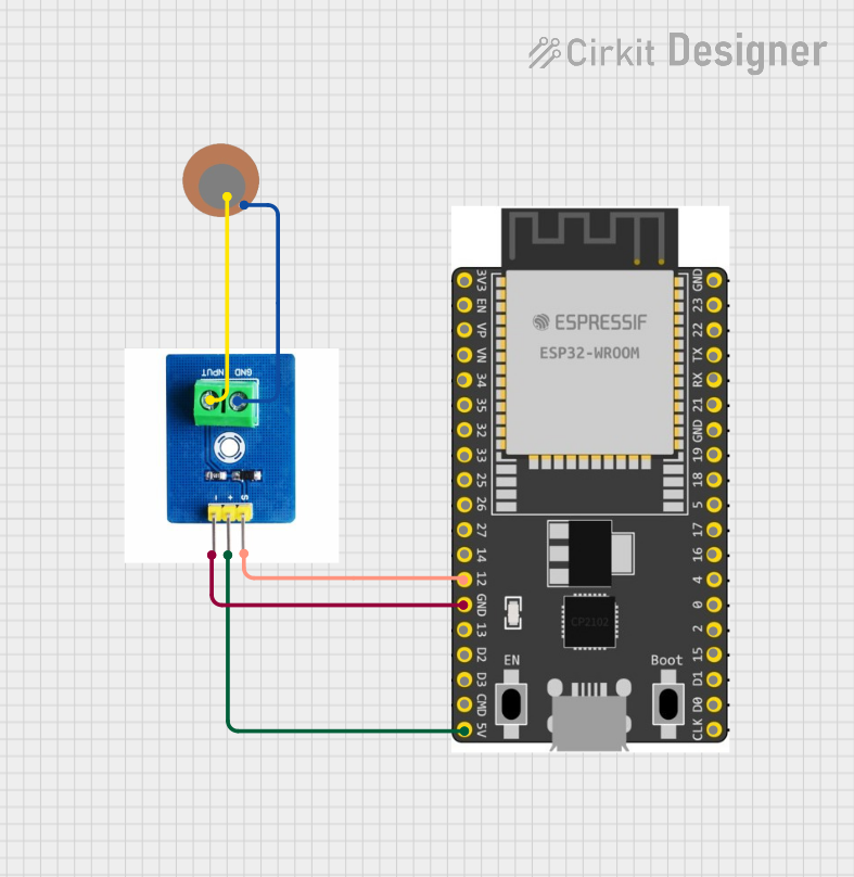
The circuit in question consists of three main components: a sensor module (SEN-0100), a piezoelectric sensor (Piezo Sensor), and a microcontroller development board (ESP 32 Wroom Dev Kit). The SEN-0100 sensor module is connected to both the piezo sensor and the ESP 32 microcontroller, facilitating the interaction between the physical sensing element and the digital processing unit. The piezo sensor detects mechanical changes, such as vibrations or pressure, and the SEN-0100 module processes these signals. The ESP 32 microcontroller is programmed to handle the sensor data for further processing or action.
Component List
SEN-0100
- Description: A sensor module designed to interface with various sensors.
- Pins: Input, Ground, -, +, S
Piezo Sensor
- Description: A sensor that generates an electrical charge in response to applied mechanical stress.
- Pins: +, -
ESP 32 Wroom Dev Kit
- Description: A powerful microcontroller development board with Wi-Fi and Bluetooth capabilities.
- Pins: 3V3, EN, VP, VN, GPIO 34, GPIO 35, GPIO 32, GPIO 33, GPIO 25, GPIO 26, GPIO 27, GPIO 14, GND, GPIO 13, SD2, SD3, CMD, V5, GPIO 23, GPIO 22, TXD, RXD, GPIO 21, GPIO 19, GPIO 18, GPIO 5, GPIO 17, GPIO 16, GPIO 4, GPIO 0, GPIO 2, GPIO 15, SD1, SD0, CLK
Wiring Details
SEN-0100
- Input: Connected to the "+" pin of the Piezo Sensor.
- Ground: Connected to the "-" pin of the Piezo Sensor.
- -: Connected to the "GND" pin of the ESP 32 Wroom Dev Kit.
- +: Connected to the "V5" pin of the ESP 32 Wroom Dev Kit.
- S: Connected to the "GPIO 14" pin of the ESP 32 Wroom Dev Kit.
Piezo Sensor
- +: Connected to the "Input" pin of the SEN-0100.
- -: Connected to the "Ground" pin of the SEN-0100.
ESP 32 Wroom Dev Kit
- GND: Connected to the "-" pin of the SEN-0100.
- V5: Connected to the "+" pin of the SEN-0100.
- GPIO 14: Connected to the "S" pin of the SEN-0100.
Documented Code
ESP 32 Wroom Dev Kit Code
void setup() {
  // put your setup code here, to run once:

}

void loop() {
  // put your main code here, to run repeatedly:

}
Note: The provided code for the ESP 32 Wroom Dev Kit is a template with empty setup and loop functions. This code should be expanded with specific instructions for initializing the sensor module and handling the data from the piezo sensor.
SEN-0100 Code
No code provided for SEN-0100 as it is not a programmable device.
Piezo Sensor Code
No code provided for Piezo Sensor as it is not a programmable device.
The documentation for the microcontroller code is currently empty. It is expected that the user will provide the specific functionality and logic to be implemented in the setup and loop functions of the ESP 32 Wroom Dev Kit.