Cirkit Designer
Your all-in-one circuit design IDE
Home /
Project Documentation
Arduino UNO Based Air Quality and Temperature Monitoring System with LCD Display
Circuit Documentation
Summary
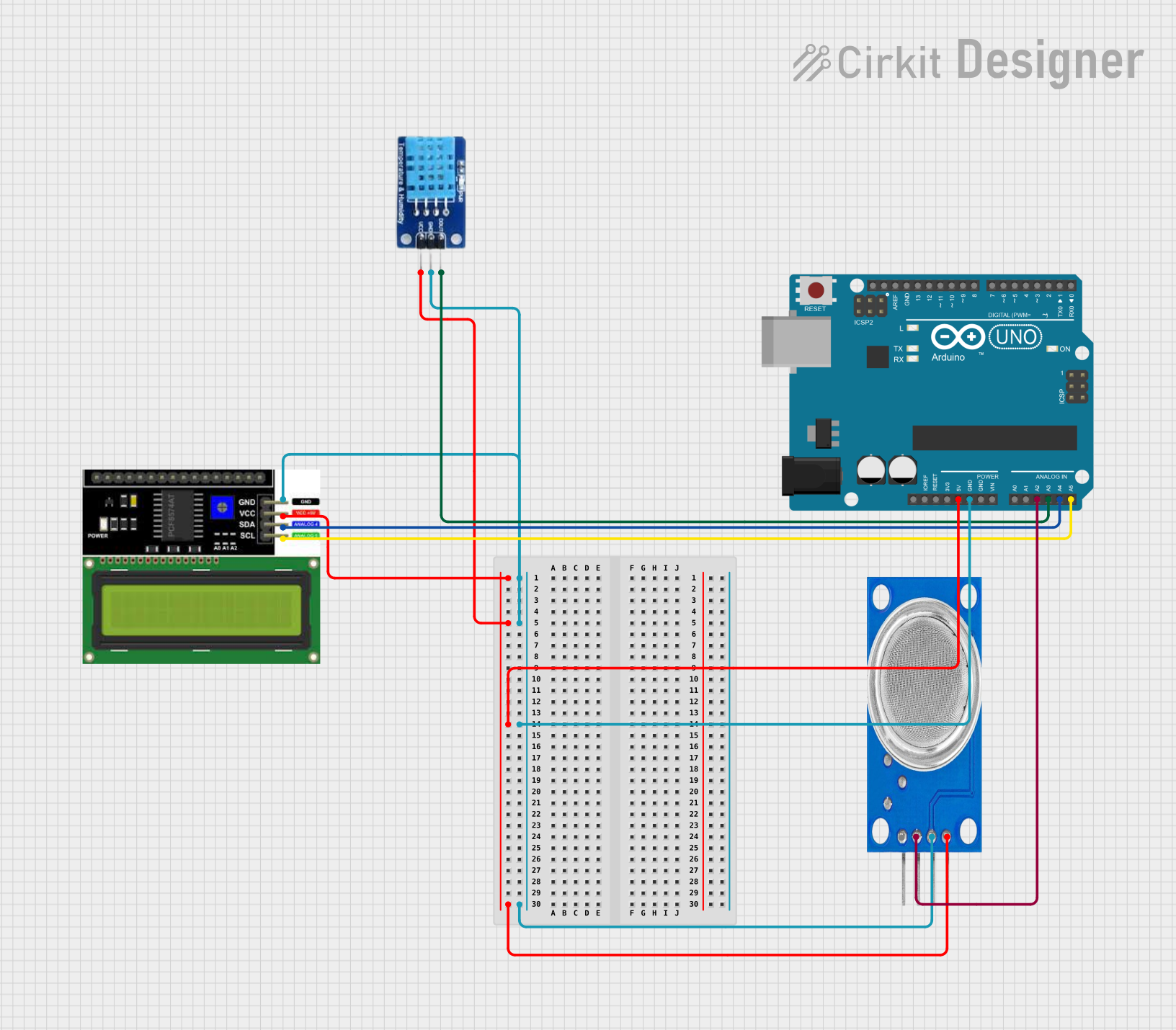
The circuit in question is designed to interface an Arduino UNO with a DHT11 temperature and humidity sensor, an MQ135 air quality sensor, and an LCD I2C display. The Arduino UNO serves as the central microcontroller unit, managing data acquisition from the sensors and displaying relevant information on the LCD. The DHT11 sensor provides temperature and humidity readings, while the MQ135 sensor is used to detect the presence of various gases in the air. The LCD display, which communicates over the I2C protocol, is used to present the sensor data to the user.
Component List
Arduino UNO
- Description: A microcontroller board based on the ATmega328P.
- Pins: UNUSED, IOREF, Reset, 3.3V, 5V, GND, Vin, A0-A5, SCL, SDA, AREF, D0-D13.
DHT11
- Description: A basic, ultra low-cost digital temperature and humidity sensor.
- Pins: DATA, GND, VCC.
MQ135
- Description: A sensor for detecting a wide range of gases, including NH3, NOx, alcohol, benzene, smoke, and CO2.
- Pins: VCC, GND, A0, D0.
LCD I2C Display
- Description: A liquid crystal display that communicates via the I2C bus interface.
- Pins: GND, VCC, SDA, SCL.
Wiring Details
Arduino UNO
- 5V connected to VCC of DHT11, MQ135, and LCD I2C Display.
- GND connected to GND of DHT11, MQ135, and LCD I2C Display.
- A2 connected to A0 of MQ135.
- A3 connected to DATA of DHT11.
- A4 (SDA) connected to SDA of LCD I2C Display.
- A5 (SCL) connected to SCL of LCD I2C Display.
DHT11
- DATA connected to A3 of Arduino UNO.
- GND connected to GND of Arduino UNO.
- VCC connected to 5V of Arduino UNO.
MQ135
- A0 connected to A2 of Arduino UNO.
- GND connected to GND of Arduino UNO.
- VCC connected to 5V of Arduino UNO.
LCD I2C Display
- SDA connected to A4 (SDA) of Arduino UNO.
- SCL connected to A5 (SCL) of Arduino UNO.
- GND connected to GND of Arduino UNO.
- VCC connected to 5V of Arduino UNO.
Documented Code
Arduino UNO Code (sketch.ino)
void setup() {
  // put your setup code here, to run once:

}

void loop() {
  // put your main code here, to run repeatedly:

}
Additional Notes
- The provided code is a template and does not contain any functional code for sensor data acquisition or display on the LCD.
- The user is expected to implement the setup and loop functions to initialize the sensors, read data from them, and display the information on the LCD screen.
- The DHT11 and MQ135 sensors will require libraries for interfacing with the Arduino, which should be included at the beginning of the code.
- The LCD I2C Display will also require a library for I2C communication, which should be initialized in the setup function.