
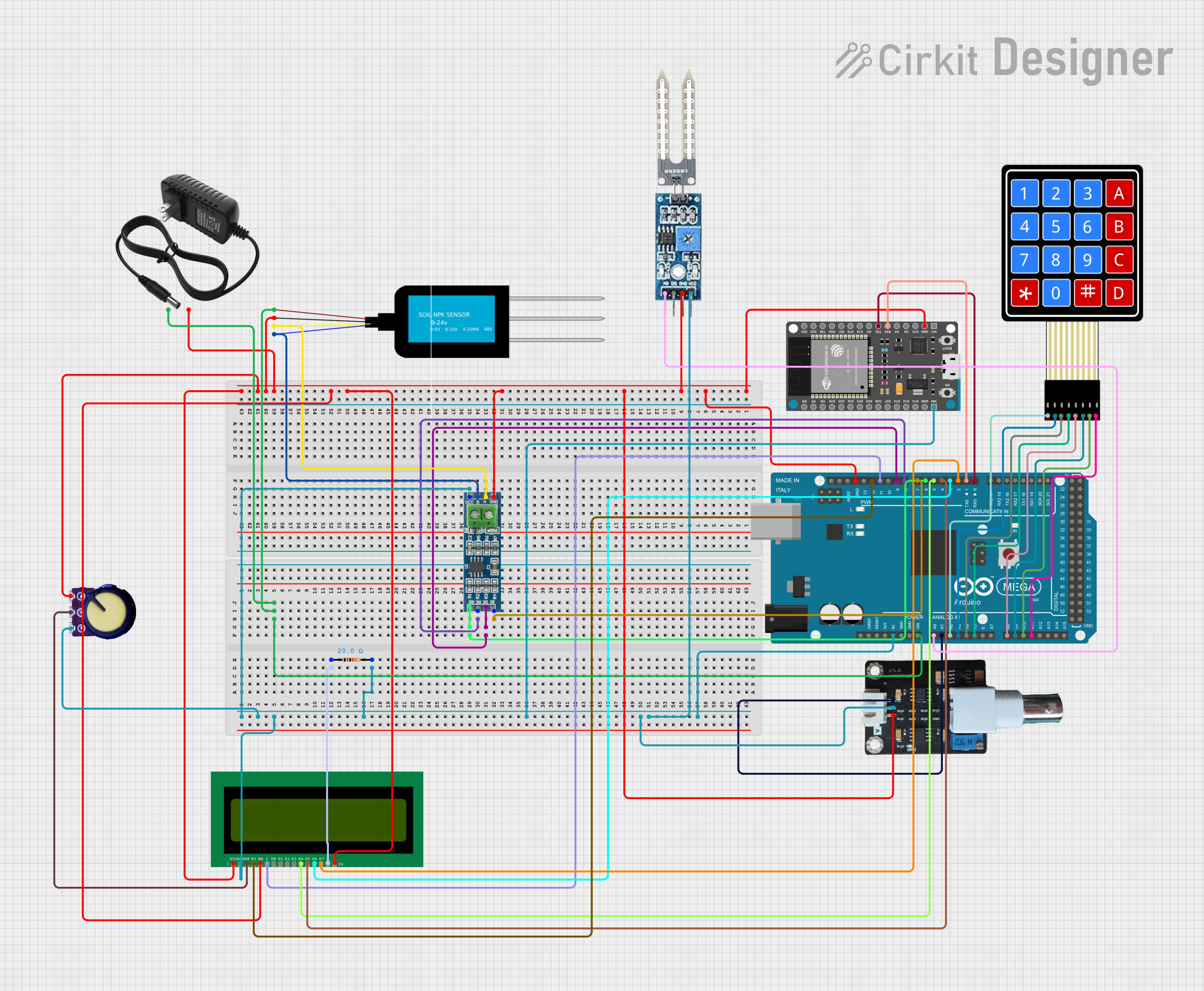
Circuit Documentation
Summary
This circuit integrates various sensors and modules with an Arduino Mega 2560 and an ESP32 Devkit V1. The sensors include an NPK Soil Sensor, Soil Moisture Interceptor, pH Meter, Water Sensor, and a 16X2 LCD for display. Additionally, a 4X4 Membrane Matrix Keypad is used for user input. The circuit is powered by a 12V power supply and includes a potentiometer for adjustable voltage.
Component List
NPK Soil Sensor (mini)
- Pins: VCC, GND, A, B
- Description: Measures the nitrogen, phosphorus, and potassium levels in the soil.
ESP32 Devkit V1
- Pins: 3V3, GND, D15, D2, D4, RX2, TX2, D5, D18, D19, D21, RX0, TX0, D22, D23, EN, VP, VN, D34, D35, D32, D33, D25, D26, D27, D14, D12, D13, VIN
- Description: A microcontroller with Wi-Fi and Bluetooth capabilities.
Arduino Mega 2560
- Pins: IOREF, RESET, 3V3, 5V, GND, VIN, A0-A15, D0-D53, PWM pins, AREF, SDA, SCL
- Description: A microcontroller board based on the ATmega2560.
Soil Moisture Interceptor
- Pins: AO, DO, GND, VCC
- Description: Measures the moisture content in the soil.
Water Sensor
- Pins: -, +
- Description: Detects the presence of water.
pH Meter V1.1
- Pins: DATA, VCC, GND
- Description: Measures the pH level of a solution.
16X2 LCD
- Pins: VSS, VDD, V0, RS, RW, E, D0-D7, A, K
- Description: A 16x2 character LCD display.
4X4 Membrane Matrix Keypad
- Pins: R1, R2, R3, R4, C1, C2, C3, C4
- Description: A keypad with 4 rows and 4 columns for user input.
Potentiometer
- Pins: GND, Output, VCC
- Description: A variable resistor used to adjust voltage.
12V Power Supply
- Pins: +, -
- Description: Provides 12V power to the circuit.
Resistor
- Pins: pin1, pin2
- Description: A 20 Ohms resistor.
RS-485 Module
- Pins: VCC, B, A, GND, RO, RE, DE, DI
- Description: A module for RS-485 communication.
Wiring Details
NPK Soil Sensor (mini)
- VCC connected to 12V Power Supply (+)
- GND connected to Common Ground
- A connected to RS-485 Module (A)
- B connected to RS-485 Module (B)
ESP32 Devkit V1
- VIN connected to Common VCC
- GND connected to Common Ground
- TX2 connected to Arduino Mega 2560 (D0 RX0)
- RX2 connected to Arduino Mega 2560 (D1 TX0)
Arduino Mega 2560
- VIN connected to 12V Power Supply (+)
- 5V connected to Common VCC
- GND connected to Common Ground
- A0 connected to Soil Moisture Interceptor (AO)
- A1 connected to pH Meter V1.1 (DATA)
- A2 connected to 4X4 Membrane Matrix Keypad (R1)
- A3 connected to 4X4 Membrane Matrix Keypad (R2)
- A4 connected to 4X4 Membrane Matrix Keypad (R3)
- A5 connected to 4X4 Membrane Matrix Keypad (R4)
- A8 connected to 4X4 Membrane Matrix Keypad (C1)
- A9 connected to 4X4 Membrane Matrix Keypad (C2)
- A10 connected to 4X4 Membrane Matrix Keypad (C3)
- A11 connected to 4X4 Membrane Matrix Keypad (C4)
- D2 PWM connected to 16X2 LCD (D7)
- D3 PWM connected to 16X2 LCD (D6)
- D4 PWM connected to 16X2 LCD (D5)
- D5 PWM connected to 16X2 LCD (D4)
- D6 PWM connected to RS-485 Module (RO)
- D7 PWM connected to RS-485 Module (DI)
- D8 PWM connected to RS-485 Module (RE)
- D9 PWM connected to RS-485 Module (DE)
- D11 PWM connected to 16X2 LCD (E)
- D12 PWM connected to 16X2 LCD (RS)
Soil Moisture Interceptor
- VCC connected to Common VCC
- GND connected to Common Ground
- AO connected to Arduino Mega 2560 (A0)
Water Sensor
- + connected to Common VCC
- - connected to Common Ground
pH Meter V1.1
- VCC connected to Common VCC
- GND connected to Common Ground
- DATA connected to Arduino Mega 2560 (A1)
16X2 LCD
- VSS connected to Common Ground
- VDD connected to Common VCC
- V0 connected to Potentiometer (Output)
- RS connected to Arduino Mega 2560 (D12 PWM)
- RW connected to Common Ground
- E connected to Arduino Mega 2560 (D11 PWM)
- D0-D7 connected to respective pins on Arduino Mega 2560
- A connected to Resistor (pin1)
- K connected to Common Ground
4X4 Membrane Matrix Keypad
- R1 connected to Arduino Mega 2560 (A2)
- R2 connected to Arduino Mega 2560 (A3)
- R3 connected to Arduino Mega 2560 (A4)
- R4 connected to Arduino Mega 2560 (A5)
- C1 connected to Arduino Mega 2560 (A8)
- C2 connected to Arduino Mega 2560 (A9)
- C3 connected to Arduino Mega 2560 (A10)
- C4 connected to Arduino Mega 2560 (A11)
Potentiometer
- GND connected to Common Ground
- Output connected to 16X2 LCD (V0)
- VCC connected to Common VCC
12V Power Supply
- + connected to Common VCC
- - connected to Common Ground
Resistor
- pin1 connected to 16X2 LCD (A)
- pin2 connected to Common VCC
RS-485 Module
- VCC connected to Common VCC
- GND connected to Common Ground
- A connected to NPK Soil Sensor (mini) (A)
- B connected to NPK Soil Sensor (mini) (B)
- RO connected to Arduino Mega 2560 (D6 PWM)
- RE connected to Arduino Mega 2560 (D8 PWM)
- DE connected to Arduino Mega 2560 (D9 PWM)
- DI connected to Arduino Mega 2560 (D7 PWM)
Documented Code
Arduino Mega 2560 Code
void setup() {
  // put your setup code here, to run once:

}

void loop() {
  // put your main code here, to run repeatedly:

}
This code is a basic template for the Arduino Mega 2560. The setup() function is used to initialize any settings or configurations, and the loop() function contains the main code that runs repeatedly.