Cirkit Designer
Your all-in-one circuit design IDE
Home /
Project Documentation
Arduino UNO Blinking LED Circuit
Circuit Documentation
Summary of the Circuit
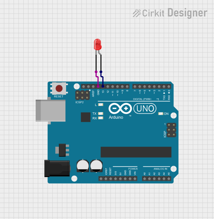
This circuit consists of an Arduino UNO microcontroller board that controls a two-pin red LED. The LED is connected to the Arduino such that it blinks on and off with a 1-second interval. The anode of the LED is connected to digital pin D13 on the Arduino, and the cathode is connected to the ground (GND) pin on the Arduino. The embedded code uploaded to the Arduino UNO is responsible for the blinking behavior of the LED.
Component List
Arduino UNO
- Description: A microcontroller board based on the ATmega328P.
- Purpose: Acts as the control unit for the LED, providing power and signal to blink the LED.
- Pins: UNUSED, IOREF, Reset, 3.3V, 5V, GND, Vin, A0-A5, SCL, SDA, AREF, D0-D13.
LED: Two Pin (red)
- Description: A basic red light-emitting diode.
- Purpose: Emits light when powered, indicating the output from the Arduino.
- Pins: Anode, Cathode.
Wiring Details
Arduino UNO
- GND: Connected to the cathode of the LED.
- D13: Connected to the anode of the LED.
LED: Two Pin (red)
- Cathode: Connected to the GND pin on the Arduino UNO.
- Anode: Connected to the D13 pin on the Arduino UNO.
Documented Code
/*
 * This Arduino sketch controls a red LED connected to pin D13.
 * The LED will blink on and off with a 1-second interval.
 */

void setup() {
  // Initialize digital pin D13 as an output.
  pinMode(13, OUTPUT);
}

void loop() {
  // Turn the LED on (HIGH is the voltage level)
  digitalWrite(13, HIGH);
  // Wait for a second
  delay(1000);
  // Turn the LED off by making the voltage LOW
  digitalWrite(13, LOW);
  // Wait for a second
  delay(1000);
}
- File Name: sketch.ino
- Description: The code sets up pin D13 as an output to control the LED. In the loop function, it turns the LED on for one second and then off for one second, repeatedly.